
Inovance MTIO-2824RND Bedienungsanleitung
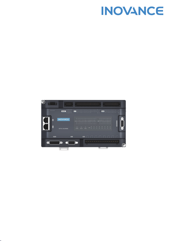
MTIO-2824RND
Multi-functional Remote I/O Module
User Guide
Suzhou Inovance Technology Co., Ltd.
Add.: No. 16 Youxiang Road, Yuexi Town, Wuzhong District,
Suzhou 215104, P.R. China
Website: http://www.inovance.com
19011178A01
*19011178A01*
1
Preface
Overview
MTIO-2824RND is a multi-functional remote I/O extension module developed and
manufactured by Inovance. Using the EtherCAT bus, this product supports up to 24
digital outputs (including 8 relay outputs and 16 common digital outputs), 28 digital
inputs, 2 analog inputs, 2 analog outputs, handwheel input terminal (including 9
digital inputs and 1 pair of phase A/B dierential quadrature pulse inputs), and servo
pulse control terminal.
This user guide describes the specications, characteristics, and usage of this product.
Please read this user guide carefully before using to ensure safety. You can obtain the
latest version of this user guide from Inovance's website (www.inovance.com).
Intended Audience
This user guide is intended for the users (including electrical engineers, software
engineers, and system engineers) of computer numerical control (CNC) machine tools
such as the engraving and milling machine and spring machine.
First Use
Read this document carefully before you use the product for the rst time. For any
doubts about functionality and performance, consult Inovance's technical support
personnel.
Standards Compliance
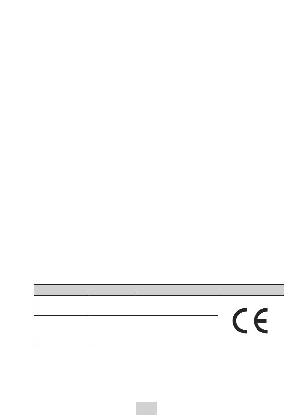
The product complies with the following directives and standards:
Directive Name Standards Compliance Mark
LVD 2014/35/EU EN 61010-1:2010
EN 61010-2-201:2013
EMC 2014/30/EU
EN 61131-2:2007
EN 55011:2016+A1:2017
IEC 61000-6-2:2016
The product complies with the LVD and EMC and is labeled with the CE mark.
LVD: 2014/35/EU; EMC: 2014/30/EU
A machine or device equipped with the product must also be labeled with the CE
mark.
2
The customer who nally assembles the machine equipped with the product is
responsible for attaching the CE mark to the machine. The customer nally conrms
whether the machine complies with the uniform European standards.
Change History
Date Issue Description
November 2019 A00 Released the rst issue.
Safety Instructions
Safety Precautions
1 ) Before installing, operating, and maintaining this equipment, read the safety
instructions and precautions thoroughly, and comply with them during
operations.
2 ) To ensure personal safety and equipment security, follow the signs on the
equipment and all the safety instructions in this user guide.
3 ) "CAUTION", "WARNING", and "DANGER" items in the user guide do not
indicate all safety precautions that need to be followed; instead, they just
supplement the safety precautions.
4 ) Use this equipment according to the designated environment requirements.
Damage caused by improper usage is not covered by warranty.
5 ) Inovance shall take no responsibility for any personal injuries or property
damage caused by improper usage.
Safety Levels and Denitions
DANGER
Indicates that failure to comply with the notice will result in severe
personal injuries or even death.
WARNING
Indicates that failure to comply with the notice may result in severe
personal injuries or even death.
CAUTION
Indicates that failure to comply with the notice may result in minor or
moderate personal injuries or equipment damage.
Keep this user guide well so that it can be read when necessary and forward this user
guide to the end user.

3
Control System Design
DANGER
◆Design a safety circuit to ensure that the control system operates safely upon power or
controller failure.
◆Do not apply this product to machines that may cause personal injuries or death,
equipment damage, or system shutdown.
CAUTION
◆When an output unit such as a relay or transistor of the controller is damaged, its
output cannot be controlled in the ON or OFF state. To ensure proper operating of
the equipment, design an external protection circuit and a safety mechanism for the
output signals related to critical incidents.
◆The controller is designed for indoor electrical environments complying with the
Class II overcurrent rating. Install a lightning protection device for the power system
to prevent lightning overvoltage on the power input terminal, signal input terminal, or
control output terminal of the controller and avoid equipment damage.
Installation
DANGER
◆Equipment installation must be performed only by professional maintenance
personnel who have been trained on necessary electrical knowledge.
◆The controller adopts the microcomputer design. Keep the controller clean and
prevent metal scraps, conductors, water, and corrosive gases or liquids from entering
it. Any noncompliance may result in a re, a malfunction, or a misoperation. Cut o
all external power supplies of the system before you install or remove a module. Any
noncompliance may result in an electric shock, a malfunction, or a misoperation.
◆Do not install this product on a ammable object or in an environment with overhigh
temperature. Any noncompliance may result in a re, a malfunction, or damage.
WARNING
◆Ensure that the ventilation plane of the controller is unblocked after installation.
Any noncompliance may result in poor heat dissipation, a re, a malfunction, or a
misoperation.
◆During installation, connect the modules to corresponding connectors reliably and
secure the hooks. Improper installation of a module may result in a misoperation, a
malfunction, or falling o.
4
Wiring
DANGER
◆Equipment wiring must be performed only by professional maintenance personnel
who have been trained on necessary electrical knowledge.
◆Before assembly, ensure that the controller and peripherals (such as the machine tool)
are properly grounded for lightning and leakage protection.
◆Cut o all external power supplies of the system before wiring. Any noncompliance
may result in an electric shock, a malfunction, or a misoperation.
◆The rated voltage of the power system for the controller must comply with the
specications. If the voltage is unstable, install a voltage regulator to ensure proper
operating of the controller.
◆Take insulation measures for cable terminals to avoid a decrease in the insulation
distance after cables are connected to the terminals. Any noncompliance may result in
an electric shock or equipment damage.
WARNING
◆The specications and installation methods for external wiring of the equipment must
comply with local power distribution regulations. A cable with a sucient diameter
must be used for reliable grounding. For details, see the wiring descriptions in the user
guide.
◆Verify the connector type before you connect a cable. Connection to a wrong connector
or a wiring mistake may result in a malfunction of a module or external equipment.
◆Tighten the bolt on the terminal block within the specied torque range. Any
noncompliance may result in a short circuit, a re, or a misoperation.
◆Do not bundle the control and communication cables with the main circuit or power
cable; instead, keep them at least 100 mm apart. Any noncompliance may result in
noise and a misoperation.
◆Use a shielded cable for input or output of high-frequency signals in application
scenarios with serious interference, to improve the interference immunity of the
system.
Maintenance
DANGER
◆Equipment maintenance must be performed only by professional maintenance
personnel who have been trained on necessary electrical knowledge.
◆Before rst power-on, cut o the loads of all external equipment to avoid internal
testing with the PLC and a danger to persons nearby because the motor may
immediately start upon power input.
5
WARNING
◆As a precision instrument, the controller must be installed or removed only by
maintenance personnel of the manufacturer or electrical control personnel of related
machinery factories. Familiarize yourself with the user guide to ensure safety during
operations such as running or stopping the equipment, modication during operating,
or forcible output.
◆Disconnect the power cable from the socket before you clean the equipment with a
wet cloth. Do not clean the equipment with liquids or detergent sprays.
◆If the equipment is unused for a long time, disconnect the power cable from the socket
to avoid equipment damage caused by excessive voltage uctuation.
Disposal
WARNING
◆The computer is congured with a real-time clock circuit powered by batteries.
Improper installation of the batteries may result in explosion. Therefore, use the same
or a similar type of batteries recommended by the manufacturer for replacement.
◆Dispose of retired batteries by following the instructions of the manufacturer. According
to the IEC 704-1:1982, the sound pressure in the place where an operator is located
must be less than or equal to 70 dB(A).
◆Disclaimer: The safety instructions comply with the IEC 704-1. Inovance assumes no
legal liability for the accuracy of the content.
CAUTION
◆Dispose of retired equipment as industrial waste and dispose of retired batteries by
following local directives.
6
Safety Signs
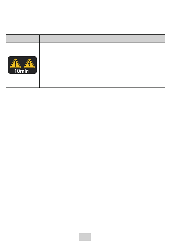
For safe equipment operation and maintenance, comply with safety signs on the
equipment, and do not damage or remove the safety labels. The following table
describes the safety signs.
Safety Sign Description
◆Read the user guide before installation and operation.
Failure to comply will result in an electric shock.
◆Do not remove the cover at power-on or within 10 minutes
after power-o.
◆Before maintenance, inspection, and wiring, cut o input
and output power, and wait at least 10 minutes until the
power indicator is o.
7
1 Product Information
■Nameplate information
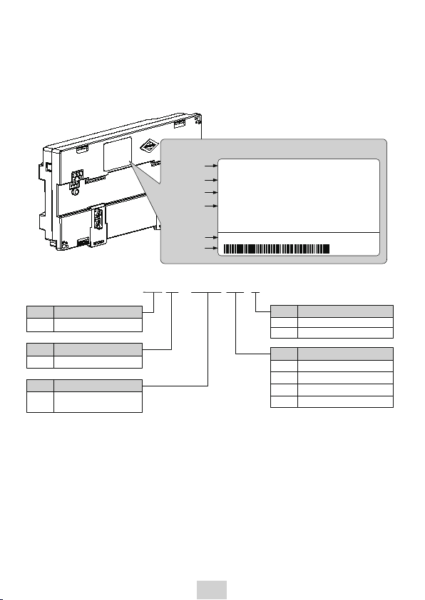
The nameplate is on the back of the product. The MTIO-2824RND module is used as an
example.
MODEL : MTIO-2824RND
Model
Rated input
Nameplate
Suzhou Inovance Technology Co.,Ltd.
Version
Barcode
POWER INPUT: 24VDC 1A
Ver: 1.0.0
SERIAL NO: 01840001xxxxxxxx
Serial No.
Rated output
OUTPUT: 24VDC 0.4A
MT IO –2824 RN D
Code Module Type
IO I/O extension module
Code Product Family
MT Machine tool
Code Output Type
Relay output
R
Code Number of I/O Channels
Inputs (two digits) + Outputs
(two digits)
RN
Transistor output (source)
TP
Code
Power Supply Type
24 VDC power supply
D
110–220 VAC power supply
A
TN Transistor output (sink)
Relay + transistor output (sink)
Four
digits
8
■Terminal type
Model Port Silkscreen Description
MTIO-2824RND
DI 28 digital inputs
DO 16 digital outputs
KM 8 relay outputs
AI-AO 2 analog inputs + 2 analog outputs
EtherCAT EtherCAT input and output
SP 1 pulse spindle control
MPG 1 handwheel signal input
EXTENSION Extension port (reserved)
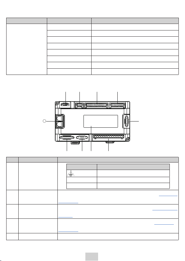
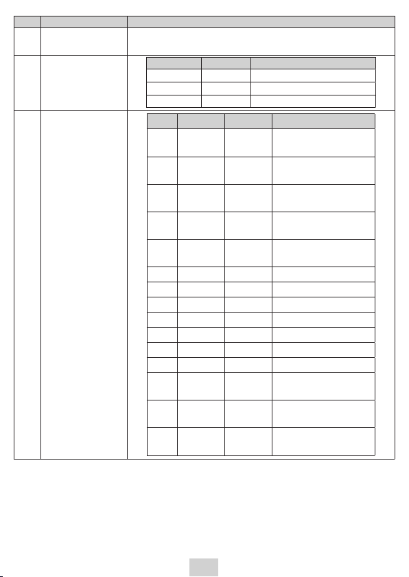
■Terminal function
① ② ③ ④
⑤
⑥⑦⑧⑨
10
No. Terminal Name Function
1 Power terminal
Mark Description
Connected to PE, case ground
0V 0 V power ground
+24V +24 V power supply
2Analog input/
output terminal
The terminal is marked as AI-AO. For its denition, see
"3Wiring"
onpage15
.
3Digital input
terminal
The terminal is marked as DI. For its denition, see
"3Wiring"on
page15
.
4Digital output
terminal
The terminal is marked as DO. For its denition, see
"3Wiring"
onpage15
.
5 Extension port The port is marked as EXTENSION. It is reserved.
9
No. Terminal Name Function
6Relay output
terminal
The terminal is marked as KM. It is used as the user control relay
output (RO) terminal.
7 Indicators
Indicator Color Denition
PWR Yellow Power indicator
RUN Green Normal running indicator
ERR Red Faulty indicator
8Spindle terminal -
SP
No. Name Direction Description
1 Sign+ Output Spindle pulse output
Sign+
2 Sign- Output Spindle pulse output
Sign-
3 Pulse+ Output Spindle pulse output
Pulse+
4 Pulse- Output Spindle pulse output
Pulse-
5 GND Digital
ground Digital signal ground
6PA- Input Encoder input PA-
7 PB+ Input Encoder input PB+
8 PB- Input Encoder input PB-
9PZ+ Input Encoder input PZ+
10 PZ- Input Encoder input PZ-
11 PA+ Input Encoder input PA+
12 COM Input Common terminal COM
13 DI Input Servo alarm input
Alarm
14 DO0 Output Servo enabling output
En
15 DO1 Output Servo reset output
Reset
Inhaltsverzeichnis
Andere Inovance E/A-System Handbücher


Beliebte E/A-System Handbücher anderer Marken

WAGO
WAGO 750-344 Bedienungsanleitung

Teknim
Teknim TWM-1887 Bedienungsanleitung

Intelligent Appliance
Intelligent Appliance IA-2662-E Bedienungsanleitung

BERGHOF
BERGHOF ECC DIO 16/16 Bedienungsanleitung

Advantech
Advantech PCM-27J3AU Installations- und Betriebshandbuch

Festo
Festo CP-E08-M12-CL Bedienungsanleitung


