
ITEM Linear Guide 6 60 PS Bedienungsanleitung

Linear Guide 6 60 PS
Linear Guide 6 60 PS Transverse Carriage
Assembly guide

2
Linear Guide 6 60 PS, Linear Guide 6 60 PS Transverse Carriage – Assembly guide
Contents
Symbols, safety .......................................................................................................................................................................................................2
General safety information ...................................................................................................................................................................................3
Correct use ...............................................................................................................................................................................................................3
Improper use.............................................................................................................................................................................................................4
Product description.................................................................................................................................................................................................4
Technical data .........................................................................................................................................................................................................4
Preparing for assembly ..........................................................................................................................................................................................6
Fitting the linear guide rail.....................................................................................................................................................................................6
Fitting the magnetic strips.....................................................................................................................................................................................7
Fitting the carriage ..................................................................................................................................................................................................8
Fitting the end caps.................................................................................................................................................................................................9
Fitting the steel strip............................................................................................................................................................................................. 10
Fitting Cover Prole LE 6 .................................................................................................................................................................................... 12
Accessories for Linear Guide 6 60 PS ............................................................................................................................................................ 13
Checklist ................................................................................................................................................................................................................ 14
Repair and maintenance .................................................................................................................................................................................... 14
Care and cleaning................................................................................................................................................................................................. 15
Disposal ................................................................................................................................................................................................................. 15
Product development and documentation .................................................................................................................................................... 15
Symbols, safety
Important information
Observe directions for disposal
Observe directions for disposal
Maintenance
Note! Failure to observe this safety instruction can result in material damage
Caution! Failure to observe this safety instruction can result in material damage or injury

3
Linear Guide 6 60 PS, Linear Guide 6 60 PS Transverse Carriage – Assembly guide
General safety information
The details and information in this installation guide are provided for the purposes of describing the product and its assembly
only. This information does not discharge users from the obligation to conduct their own assessments and checks. It is also
important to bear in mind that our products are subject to a natural process of wear and ageing.
This guide contains important information that will enable you to use the product safely and appropriately. When this product
is sold, rented out or otherwise passed on to another party, it must be handed over with this guide. You must therefore read
and follow the safety instructions set out below.
▪ All work on and with Linear Guides 6 60 PS and 6 60 PS Transverse Carriage must be performed with “safety rst” in
mind.
▪ If possible, switch off the power to the system before carrying out any work on a Linear Guide.
▪Observe the regulations pertaining to accident prevention and environmental protection that apply in the country and place
of work where the product is being used.
▪Use only item products that are in perfect working order.
▪Failure to use original spare parts will invalidate the product warranty!
▪Check the product for obvious defects.
▪Use the product only within the performance range described in the technical data.
▪ Ensure all the safety equipment associated with the product is present, properly installed and in full working order.
▪ Do not alter the position of safety equipment, circumvent it or render it ineffective.
The Linear Guide 6 60 PS and Linear Guide 6 60 PS Transverse Carriage documented here correspond to the state of the art
and take into account the general principles of safety applicable at the time this guide was published. Nevertheless, failure to
observe the safety instructions and warning notices in this guide may result in personal injury and damage to property. We will
assume no liability for any resulting damage or injury. We reserve the right to make changes that represent technical advanc-
es. Keep this guide in a place where it can be accessed by all users at any time. The general safety information applies to the
entire lifecycle of the Linear Guides.
Correct use
Linear Guide 6 60 PS is a component and must only be used in accordance with the technical data and safety requirements
set out in this document. Combining Linear Guide 6 60 PS with a drive system, motor and controller creates a partly complet-
ed machine as dened in Machinery Directive 2006/42/EC. Internal company requirements and the regulations that apply in
the country where the product is being used must be observed. You must not make any design modications to Linear Guide 6
60 PS yourself. We will assume no liability for any resulting damage or injury. You may only install, operate and maintain Linear
Guide 6 60 PS if:
▪ Linear Guide 6 60 PS has been integrated into its surroundings in a proper and safe manner.
▪You have carefully read and understood this guide.
▪ You are appropriately qualied.
▪You are authorised to do so by your company.
▪ You are using only original equipment from the manufacturer.
Linear Guide 6 60 PS is designed for indoor use.
4
Linear Guide 6 60 PS, Linear Guide 6 60 PS Transverse Carriage – Assembly guide
Improper use
Improper use is dened as any use of the product for purposes other than those authorised in this guide and under the de-
nition of correct use. The Linear Guides must be used only in accordance with their operating data. They are not suitable for
transporting people.
No liability shall be accepted for damage or injuries resulting from improper use.
Product description
Linear Guide 6 60 PS consists of two torsion-resistant prole rails and two heavy-duty bearing carriages. The guide is suitable
for precise, low-friction movements. Linear Guide 6 60 PS adds a compact and complete encapsulated guidance solution to
the item linear technology portfolio. As a parallel-running guide, it supports the overall solution when it comes to accommodat-
ing large loads and torques. Thanks to its installation dimensions of just 60x60mm and two Line 6 groves on its side anks,
the Linear Guide is very easy to integrate into constructions. The version with the standard carriage plate is complemented by
a version with a transverse carriage plate for building parallel linear technology solutions.
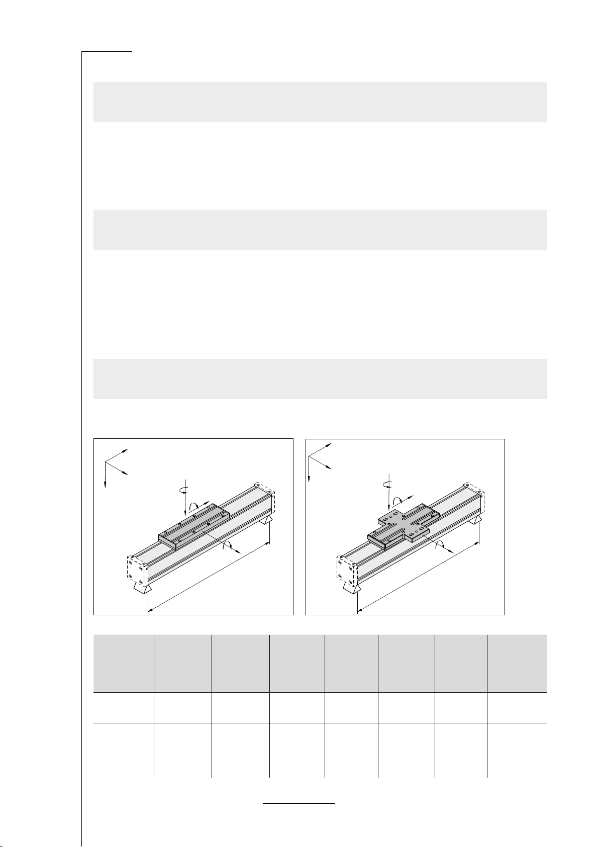
Technical data
0.0.701.69 Linear Guide 6 60 PS (zero stroke)
0.0.708.77 Linear Guide 6 60 PS Transverse Carriage (zero stroke)
L
x
y
z
Fz
Mz
Fx
Mx
Fy
My
L
x
y
z
Fz
Mz
Fx
Mx
Fy
My
Support
width Lmax at
Fzmax
[mm]
Support
width Lmax at
Fymax
[mm]
Fymax [N] Fzmax [N] Mxmax [Nm] Mymax [Nm] Mzmax [Nm]
Linear Guide
6 60 PS 650 850 2000 2000 15 120 120
Linear Guide
6 60 PS
Transverse
Carriage
650 850 2000 2000 15 120 120

5
Linear Guide 6 60 PS, Linear Guide 6 60 PS Transverse Carriage – Assembly guide
If the Linear Guide is being used in parallel with a Linear Unit, the safety clearance of the Linear Unit must be factored in
when designing the stroke.
The stroke of the Linear Guide must be extended accordingly. H = HLU + X
Linear Unit suitable for combination Art. No. HLU [mm] X [mm]
Linear Unit KLE 6 60x60 LR 0.0.605.07 0 - 2644 172
Linear Unit KGT 6 60 P20 0.0.706.00
0 - 1000 95
1001 - 1560 127
1561 - 2120 159
2121 - 2600 191
Maximum stroke: 2816mm
Basic mass: 2.2kg
Mass per mm of stroke: 3.4g/mm
Maximum acceleration: 15m/s²
Maximum speed: 1m/s
Mounting dimension: 60mm x 60mm
Ambient conditions:
Storage temperature: -20°C to +70°C
Relative humidity: 5% to 85%
Linear Guide 6 60 PS and Linear Guide 6 60 PS Transverse Carriage are intended as a permanent xture to be used in an
area that is protected from the weather.
Do not install or use in close proximity to industrial plants that produce chemical emissions.
Do not install or use in an area that is regularly exposed to high-energy surges such as those caused by presses or heavy
machinery, for example.
In case of doubt regarding resistance to certain chemicals such as test oil, alloyed oils, aggressive cleaning substances,
solvents or brake uid, we advise that you consult your specialist representative.
If using in very salty air, consult your specialist representative.
Deection in the Linear Guides should not exceed 1mm over an axis of 1000mm. In scenarios where high demands are
placed on the system dynamics, supports should be added every 300mm to 600mm.

6
Linear Guide 6 60 PS, Linear Guide 6 60 PS Transverse Carriage – Assembly guide
Preparing for assembly
Switch off the power to the system before carrying out any installation, cleaning or maintenance work on
Linear Guide 6 60 PS.
Preparations for assembly:
▪ Prole 6 60 LE: Prole length = H+204
▪ Prole, guide rail: 20mm shorter than Prole 6 60 LE
▪ Magnetic strip: Approx. 5mm longer than Prole 6 60 LE
▪ Steel strip: Approx. 12mm longer than Prole 6 60 LE
The rst step is to countersink the core bores of Support Prole 6 60 KGT on both sides and give them an M5x15 thread.
The tap should have a helix to prevent it from canting in the core hole.
Fitting the linear guide rail
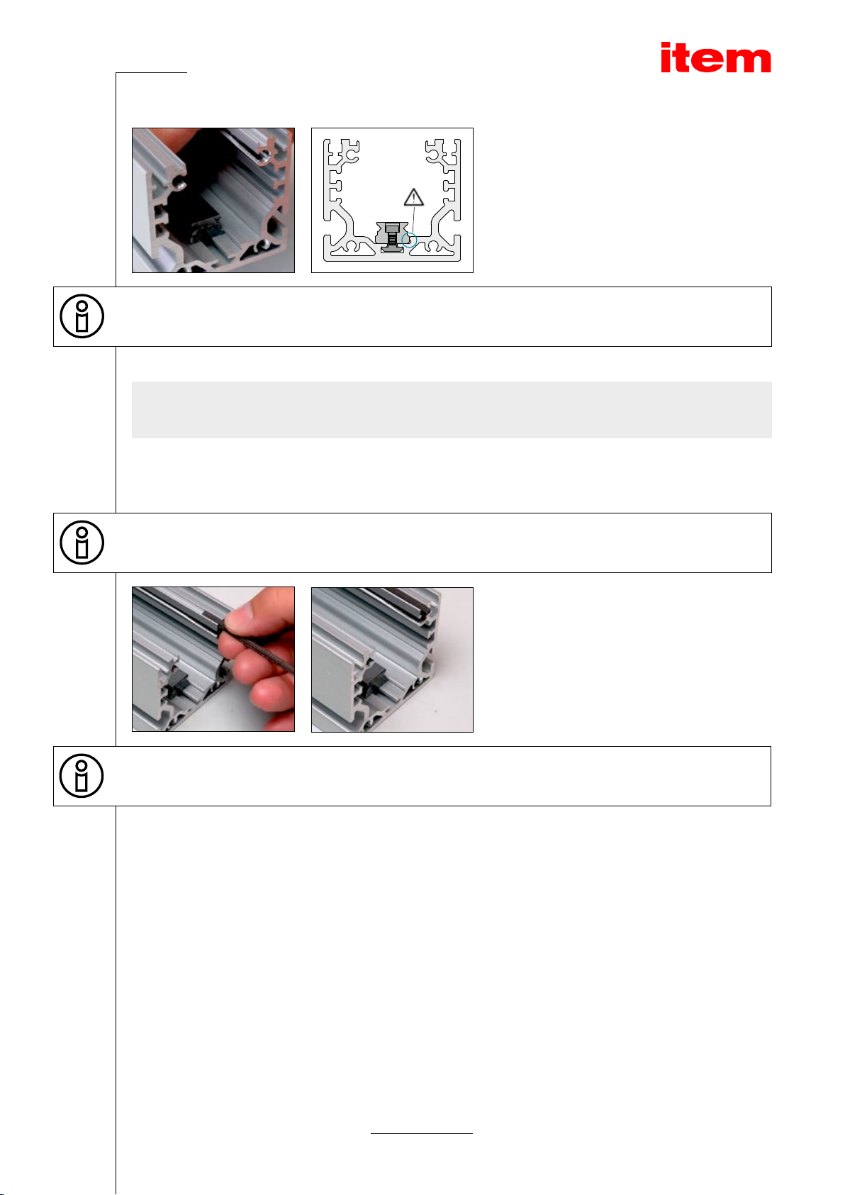
Anti-slip aids should be placed underneath the axis during assembly.
The next step is to t the linear guide rail. Start by
checking the sawn ends of the rail are burrless and
rework them if necessary.
Fit the rail with all the necessary
Hexagon Socket Head Cap Screws and T-Slot Nuts.
Make sure the Hexagon Socket Head Cap Screws are
screwed approximately one to a maximum of two full
turns into the T-Slot Nuts. This makes it easier to then
push the rail into the Support Prole.
Push the rail, tted with the
Hexagon Socket Head Cap Screws and T-Slot Nuts, into
the Support Prole. The T-Slot Nuts must be correctly
aligned when sliding the rail into its groove.
7
Linear Guide 6 60 PS, Linear Guide 6 60 PS Transverse Carriage – Assembly guide
The rail is a total of 20mm shorter than the Support
Prole and must be centred, that is to say 10mm from
each edge. Furthermore, manual pressure must be
applied to keep the rail pressed permanently against
the stop edge while the screws are being tightened.
Tightening torque MT = 1.2Nm
When tightening the screws, use your hand to keep the rail pressed against the stop edge.
Fitting the magnetic strips
The next step is to t the magnetic strips that have been cut to size. These strips will subsequently hold the Linear Guide’s
steel strip in place. They should be approximately 5mm longer than the Support Prole. Push the magnetic strips into the
Support Prole on the right-hand and left-hand sides.
Use an appropriate tool to remove any burrs from the edge of the prole where the strip is being inserted. Applying soapy
water makes it easier to push in the strips.
Once they have been tted, the magnetic
strips protrude by approximately 2.5mm at
both ends of the prole.
The ne groove in the magnetic strip should be facing up when it is being tted.

8
Linear Guide 6 60 PS, Linear Guide 6 60 PS Transverse Carriage – Assembly guide
Fitting the carriage
Ensure the relevant assembly aid of the Bearing Carriages (recirculating ball guide carriages) does not slip out. If this
happens, balls could be lost.
Place the two Bearing Carriages underneath the
carriage and also screw these in place.
Tightening torque MT: Tighten by hand and then loosen
again by a ¼ turn
Now carefully push the body of the carriage into the
Support Prole, with the Bearing Carriages sliding off
their assembly aids and directly onto the linear guide
rail.
Make sure no balls are lost. If they are, the Bearing Carriage will be unusable.
The assembly aids should be pressed against the linear guide rail continuously during installation.
9
Linear Guide 6 60 PS, Linear Guide 6 60 PS Transverse Carriage – Assembly guide
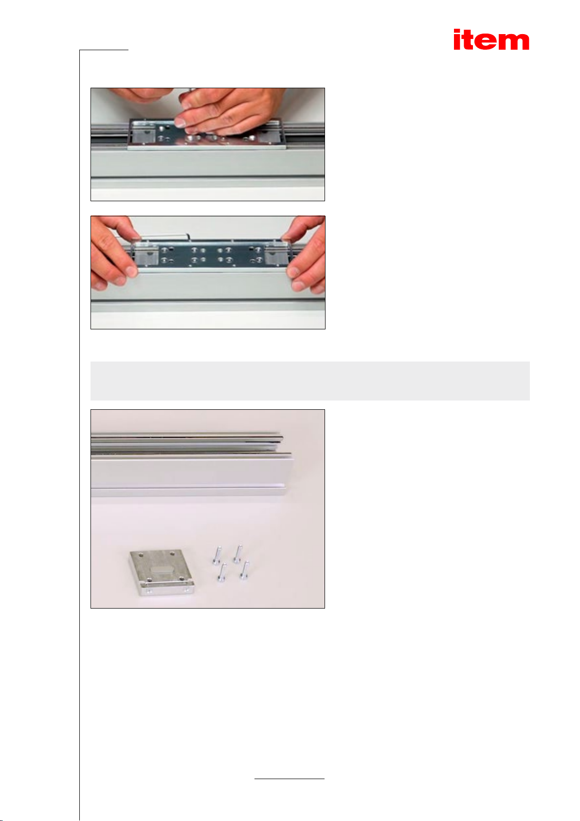
Next, screw the intermediate carriage plate securely
onto the body of the carriage using the eight Counter-
sunk Screws M4x10.
Tightening torque MT = 3Nm
Use the installed intermediate carriage plate to
align the moving carriage so that it is parallel with
and centred in relation to the Support Prole.
Then securely tighten the Bearing Carriage’s eight
Hexagon Socket Head Cap Screws.
Tightening torque MT = 1.5Nm
Fitting the end caps
Use four Hexagon Socket Head Cap Screws M5x20
each to screw the two end caps to the right and left
ends of the prole. Ensure the end caps are centred on
and parallel with the Support Prole then tighten the
screw xings.
Tightening torque MT: 2.5Nm
10
Linear Guide 6 60 PS, Linear Guide 6 60 PS Transverse Carriage – Assembly guide
Once everything has been properly tted and screwed into place, move the carriage over the entire length of the axis byhand,
checking the operation and smooth running of the guide.
Fitting the steel strip
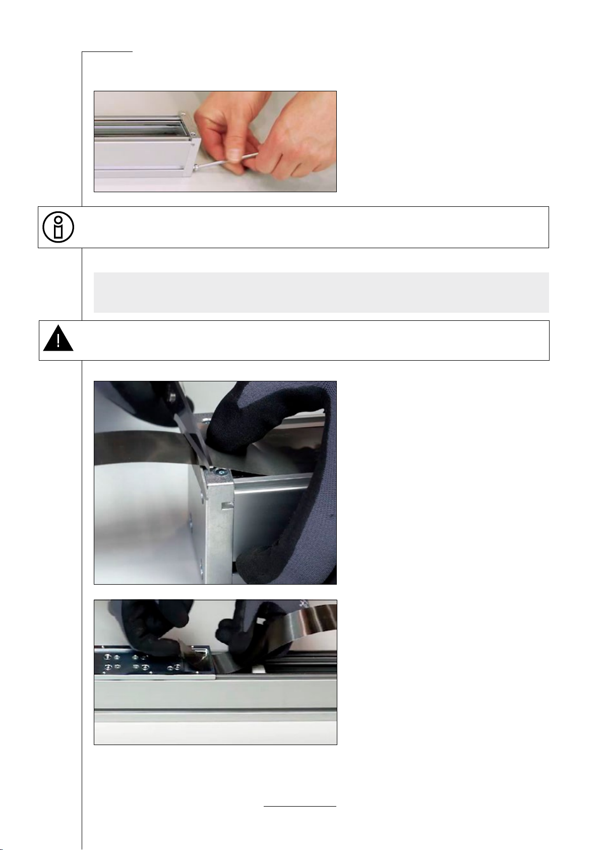
Caution: Wear cut-resistant gloves to prevent injuries when installing the steel strip.
Fit the steel strip, which covers the spindle in the pro-
le. This strip should be approximately 12mm longer
than the Support Prole.
Start by threading the steel strip from
either end, from below, through the opening in the
intermediate carriage plate and pull it through approxi-
mately 200mm.
Dieses Handbuch passt für folgende Modelle
1
Inhaltsverzeichnis
Andere ITEM Industrieanlagen Handbücher

ITEM
ITEM PS 4-25 Betriebsanleitung

ITEM
ITEM PS 4-20 Bedienungsanleitung

ITEM
ITEM PS 4-15 Betriebsanleitung

ITEM
ITEM Table Column Set 2 E HD ESD 230V Bedienungsanleitung

ITEM
ITEM KLE 5 40x40 LR Betriebsanleitung

ITEM
ITEM LED Light Fitting 15W Betriebsanleitung

ITEM
ITEM KRF 8 80x40 ZR Betriebsanleitung

ITEM
ITEM KLE 6 60x60 LR Bedienungsanleitung

ITEM
ITEM KLE 6 Betriebsanleitung

ITEM
ITEM Linear Unit LRE 8 D14 80x40 KU 80 Betriebsanleitung


