JS Automation Corp DIO8265 Bedienungsanleitung


2
Contents
1. Forward ............................................................................................................................................ 5
2. Features ............................................................................................................................................ 6
2.1 Main card..................................................................................................................................6
2.2 DIN rail mounted wiring board ................................................................................................6
3. Specifications ................................................................................................................................... 7
3.1 DIO8265Main card...................................................................................................................7
3.2 DIN rail mounted wiring board ................................................................................................8
4. Layout and dimensions..................................................................................................................... 9
4.1 DIO8265 Main card..................................................................................................................9
4.2 ADP8265DIN(R) DIN rail mounted wiring board.................................................................10
4.3 JS51050 for JM0 25PM DIN rail mounted dummy wiring board..........................................10
5. PIN definitions ............................................................................................................................... 11
5.1 Pin definitions for DIO8265_JF0 connector...........................................................................11
5.2 Pin definitions for DIO8265_JM0 connector .........................................................................12
6. I/O interface diagram...................................................................................................................... 13
6.1 TTL IO....................................................................................................................................13
6.2 Isolated output diagram ..........................................................................................................13
7. External wiring diagram................................................................................................................. 14
8. Hardware settings........................................................................................................................... 15
8.1 CARD ID setting ....................................................................................................................15
8.2 Jumper setting.........................................................................................................................15
9. Applications.................................................................................................................................... 16
10. Ordering information...................................................................................................................... 17

3
Notes on hardware installation
Please follow step by step as you are installing the control cards.
1. Be sure your system is power off.
2. Be sure your external power supply for the wiring board is power off.
3. Plug your control card in slot, and make sure the golden fingers are put in right contacts.
4. Fasten the screw to fix the card.
5. Connect the cable between the card and wiring board.
6. Connect the external power supply for the wiring board.
7. Recheck everything is OK before system power on.
8. External power on.
Congratulation! You have it.
For more detail of step by step installation guide, please refer the file
“..\download\Supplemental_technical_data\Step_by_step_installation_of_Contrl_Card.pdf “on the CD
come with the product or download the complementary documents from
http://www.automation.com.tw/common/Supplemental_technical_data.htm

4
Warranty
The DIO8265 is warranted against defects in materials and workmanship for a period of two years
from the date of shipment, as evidenced by receipts or serial no. on board. JS automation Corp. will, at
its option, repair or replace product that proves to be defective during the warranty period. This warranty
includes parts, labor and shipping costs of returning.
Except as specified herein, JS automation Corp. makes no warranties, express or implied, and
specifically disclaims any warranty of merchantability or fitness for a particular purpose. Customer’s
right to recover damages caused by fault or negligence on the part of JS automation Corp. shall be
limited to the amount theretofore paid by the customer. JS automation Corp. will not be liable for
damages resulting from loss of data, profits, use of products, or incidental or consequential damages,
even if advised of the possibility thereof. This limitation of the liability of JS automation Corp. will
apply regardless of the form of action, whether in contract or tort, including negligence. Any action
against JS automation Corp. must be brought within one year after the cause of action accrues.
JS automation Corp. shall not be liable for any delay in performance due to causes beyond its reasonable
control. The warranty provided herein does not cover damages, defects, malfunctions, or service failures
caused by owner’s failure to follow the JS automation Corp. installation, operation, or maintenance
instructions; owner’s modification of the product; owner’s abuse, misuse, or negligent acts; and power
failure or surges, fire, flood, accident, actions of third parties, or other events outside reasonable control.
If any defect occurs, you should email to us as the following form to get the fast response:
Detailed Company Information
Company/Organization:
Contact Person:
E-mail:
Address:
Country:
Tel/Fax:
Web Site:
Product information
product model:
serial no.:
Environment to Use: such as CPU board, Operating System, target application...
description of defect: (as detail as possible)

5
1. Forward
Thank you for your selection of JAC’s product DIO8265 64 outputs DIGITAL I/O card for
industrial PC. In the field of industrial control, digital I/O is generally controlled under a microprocessor
and owing to their specific consideration of industrial environment, it is quite different from the
laboratory requirement.
Our experience in the noise immunity makes this card very stable in the noisy environment and you
don’t worry about computer down by external noise. We wish the card that will be helpful to your
project.
Other DIO series products:
DIO9201 16 channel input and 16 channel output isolated digital I/O card (ISAbus)
DIO3206 48 channel TTL digital I/O Card (PCI bus)
DIO3208B 8 channel input and 8 channel relay output isolated digital I/O card (PCI bus)
DIO3216B 16 channel input and 16 channel output isolated digital I/O card (PCI bus)
DIO3217 16 channel input and 16 channel output isolated digital I/O card (PCI bus)
with multifunction timer/counter
DIO3232A/B 32 channel input and 32 channel output isolated digital I/O card (PCI bus)
DIO3248A/B 48 channel input and 16 channel output isolated digital I/O card (PCI bus)
DIO3264A/B 64 channel input isolated digital I/O card (PCI bus)
DIO3265 64 channel output isolated digital I/O card (PCI bus)
DIO8216 16 channel input and 16 channel output isolated digital I/O card (PCIe bus)
DIO8217 16 channel input and 16 channel output isolated digital I/O card (PCIe bus)
with multifunction timer/counter
DIO8232 32 channel input and 32 channel output isolated digital I/O card (PCIe bus)
DIO8264 64 channel input isolated digital I/O card (PCIe bus)
DIO4264 64 TTL digital I/O (PC-104 Module)
DIO6208 8 channel input and 8 channel relay output isolated digital I/O (PCI-104 Module)
DIO6216 16 channel input and 16 channel relay output isolated digital I/O (PCI-104 Module)
Any comment is welcome,
please visit our website
http://www.automation.com.tw/
http://www.automation-js.com/ for the up to date information.

6
2. Features
2.1 Main card
2.1.1 PCIe plug and play function with card ID for 16 identical cards
2.1.2 64 isolated DO channels
2.1.3 High voltage isolation on all isolated channel (2500 Vac)
2.1.4 Programmable debounce for TTL input
2.1.5 No output transition during start-up
2.1.6 Output status readback
2.1.7 External triggered interrupt (TTL IO07~IO00)
2.1.8 Input counter / frequency counter (on TTL IO07~IO00)
2.1.9 Keep output state after hot reset (jumper selectable)
2.1.10 Watch dog timer with default output on OUT07~OUT00
2.1.11 32bit timer with time up interrupt
2.2 DIN rail mounted wiring board
2.2.1 LEDs for corresponding status indication
2.2.2 8 digits per I/O group with Green LED at first digit
2.2.3 Optional Relay type output for different application requirement

7
3. Specifications
3.1 DIO8265Main card
Input Section
3.1.1 Interrupt : at TTL IO07~IO00
3.1.2 Counter/frequency counter : 16 bit at TTL IO07~IO00
Output Section
3.1.3 Output : 64 photo-isolated
3.1.4 Output rating : 3A @250Vac, 30Vdc (Relay)
TTL IO
3.1.5 Port : 2
3.1.6 Direction : software programmable on port base
3.1.7 Software debounce : No debounce, up to 8MHz
Timer 3.1.8 Length : 32 bit @1us
3.1.9 Interrupt : time up interrupt
Main Card General
3.1.10 Card ID : 4 bits
3.1.11 Insulation resistance : 100M Ohm (min) at 1000Vdc
3.1.12 Isolation voltage : 2500Vac 1Min
3.1.13 Connector : Centronic type SCSI II 68pin connector
3.1.14 Operation temperature : 0 to +70 degree C
3.1.15 Storage temperature : -20 to +80 degree C
3.1.16 Operation humidity : 5~95% RH, non-condensing
3.1.17 Dimensions : 165(W) * 110(H) mm , 6.5(W) * 4.4(H)in

8
3.2 DIN rail mounted wiring board
ADP8265DIN(R) DIN rail mounted wiring board
3.2.1 External supply : DC 24V±4V
3.2.2 Output status indicator : 64 LED, 8 digit per group with Green LED at first digit
3.2.3 Power indicator : Red LED
3.2.4 Output capacity : Relay : 3A continuous@250Vac(max)
3.2.5 Operation temperature : 0 to 70°C
3.2.6 Operation humidity : RH5~95%, non-condensed
3.2.7 Dimension : ADP8265DIN(R) : 274(W) * 107(L) * 45(H)mm
10.8(W) * 4.3(L) * 1.8(H)in
JS51050 25PM DIN rail mounted dummy wiring board for TTL I/O
3.2.8 Connection cable : D-type 25P cable to connect main and wiring board
3.2.9 Dimension : 86(W)*79(L)*52(H)mm , 3.4(W)*3.2(L)*2.1(H)in
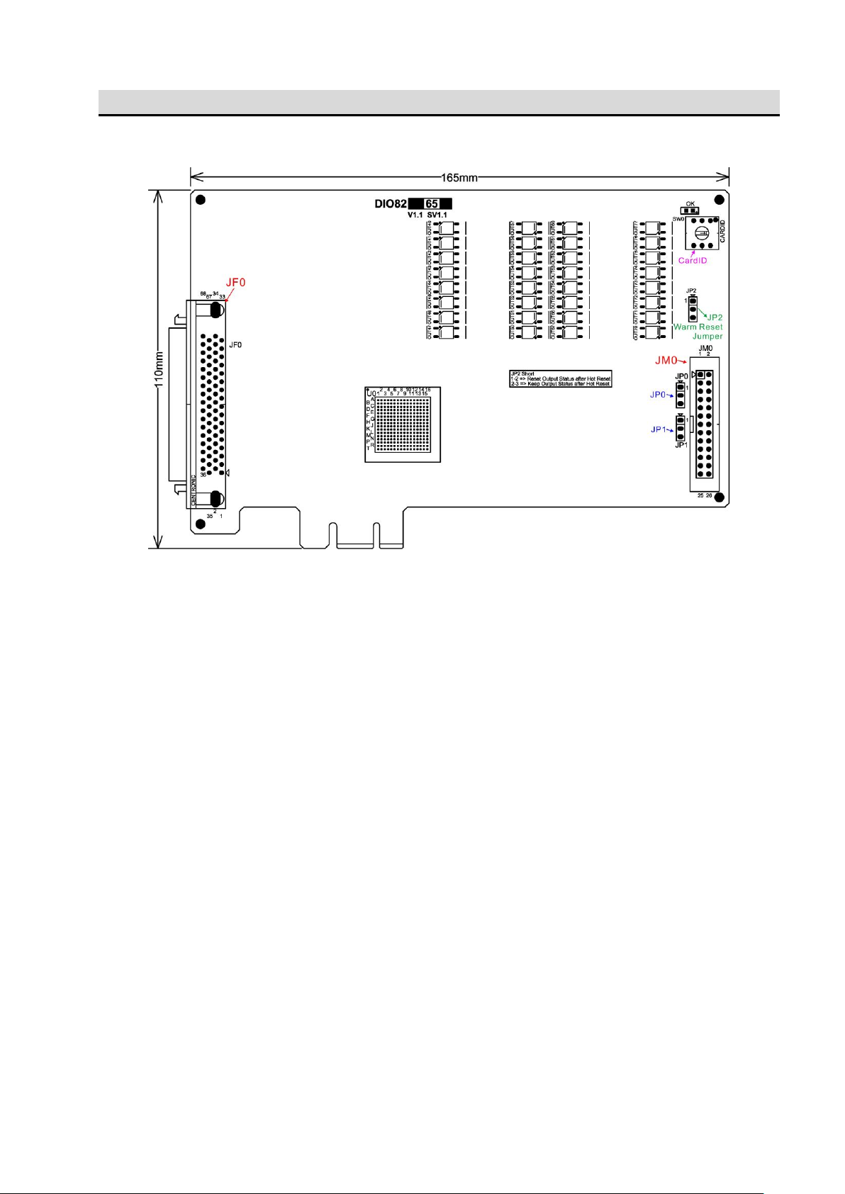
9
4. Layout and dimensions
4.1 DIO8265 Main card
*dimension in bare board
Inhaltsverzeichnis
Andere JS Automation Corp E/A-System Handbücher

Beliebte E/A-System Handbücher anderer Marken

WAGO
WAGO 750-344 Bedienungsanleitung

Teknim
Teknim TWM-1887 Bedienungsanleitung

Intelligent Appliance
Intelligent Appliance IA-2662-E Bedienungsanleitung

BERGHOF
BERGHOF ECC DIO 16/16 Bedienungsanleitung

Advantech
Advantech PCM-27J3AU Installations- und Betriebshandbuch

Festo
Festo CP-E08-M12-CL Bedienungsanleitung


