
Kasco CertiSafe PM-100 Bedienungsanleitung
PM-100 PIPE MOUNT MANUAL 1
PM-100
PIPE MOUNT
Assembly &
Installation
Manual
Document number 852113
Document version number 2021.2.0

PM-100 PIPE MOUNT MANUAL 1
715.262.4488
TABLE OF CONTENTS
QUESTIONS?
Safety First�������������������������������������������������������������������������������������������������������������������������������2
Product & Installation Overview�������������������������������������������������������������������������������������������3
Suggested Tools and Supplies�����������������������������������������������������������������������������������������������3
Parts Included List ������������������������������������������������������������������������������������������������������������������4
Parts Included Illustration �����������������������������������������������������������������������������������������������������5
Tank Penetration ��������������������������������������������������������������������������������������������������������������������6
Mount Assembly ���������������������������������������������������������������������������������������������������������������������8
Cable Support������������������������������������������������������������������������������������������������������������������������13
Mixer Maintenance Recommendations�����������������������������������������������������������������������������14
Mixer Warranty ���������������������������������������������������������������������������������������������������������������������15
Non-warranty Repairs����������������������������������������������������������������������������������������������������������16
Repair Contact Form ������������������������������������������������������������������������������������������������������������17
PM-100 PIPE MOUNT MANUAL 2
IMPORTANT: PLEASE READ THIS MANUAL AND SAVE FOR FUTURE REFERENCE
Moving Machinery
WARNINGS:
Shock Hazard
• Under NO circumstances should anyone enter the water with the mixer connected or in operation.
• Running the unit out of water will create a dangerous situation and damage the seals.
• NEVER lift the unit by the power cord. If you need to remove the mixer, use the installation or mount
apparatus.
• The unit must be connected to a GFCI-protected circuit.
• Comply with local and national wiring standards during any electrical service disconnect.
• Consult a qualied professional for electrical installation.
• Use all Personal Protective Equipment necessary for safe ingress, installation, and egress from the
work site.
• Refer to applicable national and local laws and standards to facilitate the safe installation of a
CertiSafe Tank Mixer. These may include but are not limited to OSHA, CCOHS, and other regulations
related to:
• Working over or near water
• Fall protection systems
• Falling object protection systems
• Electrical standards
• Illumination
• Ventilation
• Installation of CertiSafe™ Tank Mixers requires entry into environments that pose potential hazards,
such as those described in section 1910.146 of OSHA’s Occupational Safety and Health Standards for
Permit-required conned spaces. As such:
• Observe any applicable pre-entry measures required by the entry supervisor.
• Only those authorized via the permit system in place at the installation site should participate
in installation.
• Any authorized entrant should be accompanied by at least one authorized attendant to
monitor conditions inside and outside the permit spaces during installation.
• Prior to installation, be aware of all potential fall, trip, and atmospheric hazards in the permit
space, both before and after an entrance cover is removed.
SAFETY FIRST
Back to Contents

PM-100 PIPE MOUNT MANUAL 3
PRODUCT & INSTALLATION OVERVIEW
Featuring durable stainless steel, Kasco’s PM-100 Pipe Mount positions CertiSafe™ Tank Mixers securely
within the tank for eective water movement. This manual will provide instructions for mounting a CertiS-
afe™ unit using the PM-100 and installing the entire assembly within the tank.
• Read these instructions thoroughly prior to installation.
• Contact your CertiSafe™ representative for specic recommendations as necessary.
• The cord grip and cable support equipment described here are supplied with the mixer unit.
• To prevent galling, we recommend a moisture-cured, polyurethane compound sealant suitable for con-
tact with potable water and certied to meet the shrinkage for interior and exterior use. Refer to NSF/
ANSI Standard 61 for indirect additives.
• Be aware of clearance between the mixer assembly and any xed objects within the tank, including lad-
ders, ensuring that there is enough room for the CertiSafe™ unit to function correctly and avoid damage
to any protective coatings.
• Please consult your CertiSafe™ sales representative for mixer mount placement, retrieval, and inspec-
tion requirements.
Pipe
• This kit does NOT include a pipe for mounting, as lengths will vary.
• Pre-cut the appropriate length of pipe prior to installation.
• A maximum pipe length of 10 feet is advisable. Anything greater will require additional third-party
pipe support structures.
• Once installed, about 1 foot of the pipe length should be above the upper mount assembly.
• Use 1-1/2” or 40mm (Schedule 40) stainless steel (pipe diameter 1.90” O.D.)
• The remaining length between the upper and lower mount assemblies will depend on project spec-
ications, but be mindful that as the pipe length increases, so does the potential for it to yield to
deection from the operating mixer.
• Must be schedule 40 stainless steel 300 series pipe suitable for NSF 61 applications.
Some parts will arrive pre-assembled from Kasco; however, all assembly steps are listed for reference.
Back to Contents

PM-100 PIPE MOUNT MANUAL 4
SUGGESTED TOOLS AND SUPPLIES
Pan to catch shavings
Adjustable pliers
Electric or cordless drill
Half-round metal le
3/8” drill bit 7/8” hole saw or
1-7/64” (for 10 AWG cord)
hole saw
Side cutter
3/4” wrench
9/16” wrench
9/16” socket wrench
3/4” socket wrench
Back to Contents

PM-100 PIPE MOUNT MANUAL 5
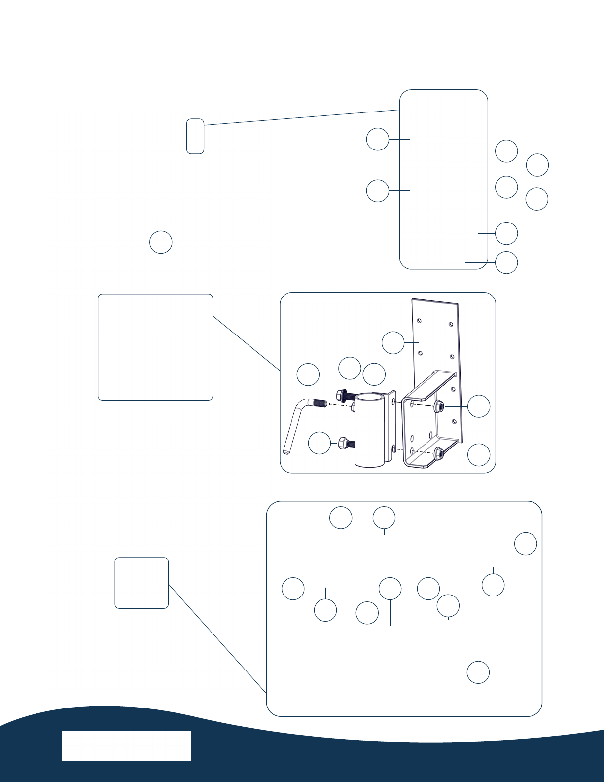
Assembly Item Description Qty Part No.
Upper mount A Upper mount base 1 997102
B Upper mount pipe bracket 1 997117
C Upper mount lock handle 1 997170
D1/2”-13 x 1-3/4” serrated ange screw 1 840531
E1/2”-13 x 1/4” shoulder screw 1 451114
FSerrated ange nut 2 840530
Lower mount G Lower mount can strap 1 997174
H Lower mount collar block 1 997172
I Lower mount strut plate 2 997176
J3/8”-16 x 5” hex head screw 2 566250
K3/8”-16 x 1” hex head screw 2 840140
L3/8” split lock washer 2 566230
M3/8”-16 nylon locknut 4 462214
Tank
Penetration
N5/16” eye bolt 1 566226
O5/16” nylon locknut 1 566202
P5/16” at washer 2 566204
Q5/16” sealing washer 1 566229
R Connecting link 1 636342
for use with Cord AWG
Ships with
CertiSafe™
mixer S Cord grip
14-16 AWG
1
997210
12 AWG 997211
10 AWG* 997212
T Cord grip nut 12-16 AWG 1997215
10 AWG 997216
U Cable support 10 AWG 1997220
12-16 AWG 997221
PARTS INCLUDED LIST
*Requires larger hole in tank roof (Ø 1-7/64”)
Back to Contents
PM-100 PIPE MOUNT MANUAL 6
PARTS INCLUDED ILLUSTRATION
N
O
P
Q
R
S
T
U
Steel tank roof
P
A
B
CD
E
G
H
M
L
J
I
K
M
K
L
M
F
F
Back to Contents
PM-100 PIPE MOUNT MANUAL 7
Ø 7/8”
Ø 3/8”
4”
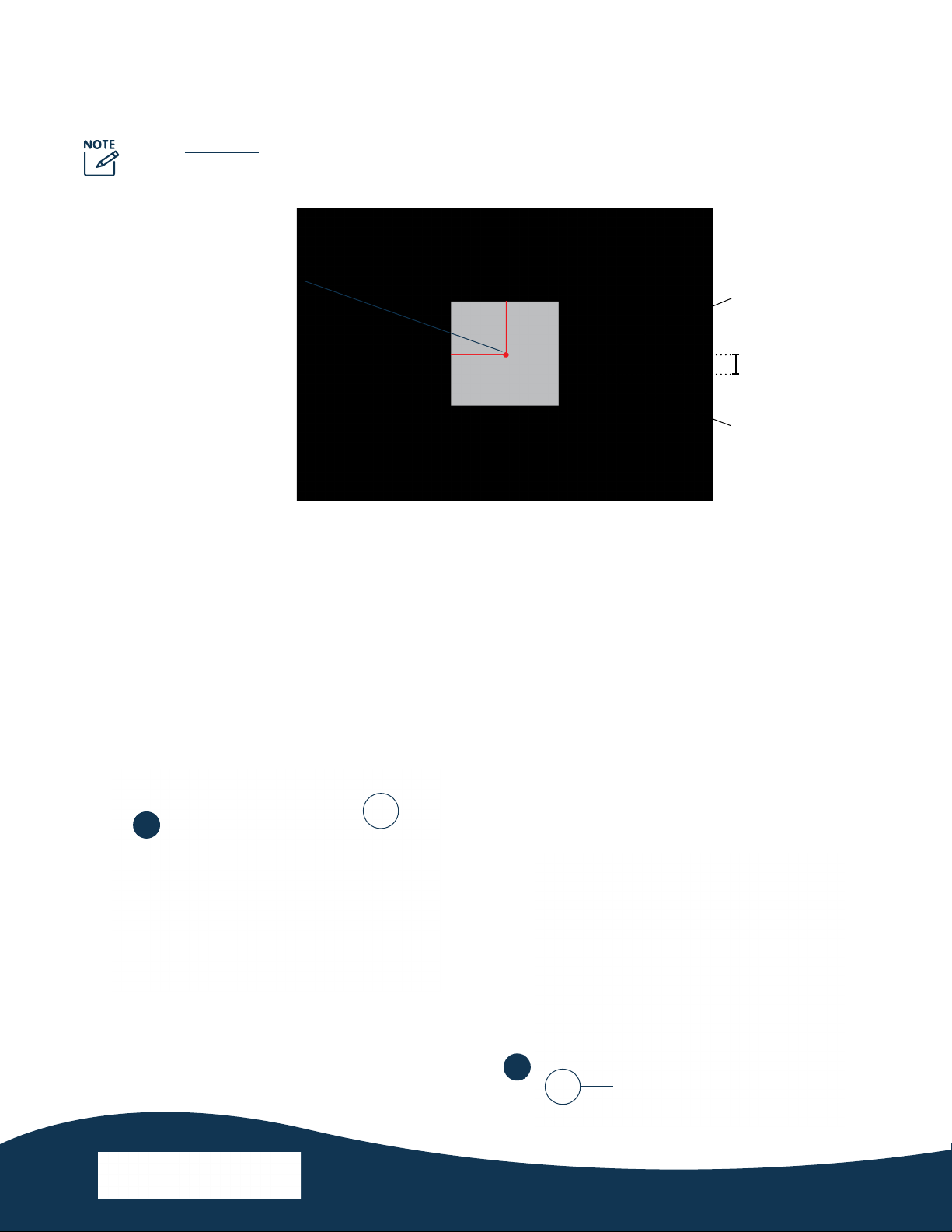
1. Drill a 7/8” (or 1-7/64” for 10 AWG cable) clearance hole through the tank at a location conveniently
reached from the tank hatch. This is for the cord grip (U).
2. Deburr both sides of the hole.
3. Drill a 3/8” clearance hole about 4” from the hole drilled in step 1. This is for the eye bolt (Q).
4. Deburr both sides of the second hole.
5. From the tank exterior, pass the O-ringed side of the cord grip (U) through the 7/8” hole, with the
O-ring outside the tank roof.
6. From the tank interior, t the cord grip nut (V) on the threads protruding into the tank.
7. Tighten the nut until snug, being careful not to over-tighten.
Tank hatch center point
TANK PENETRATION
• The maximum tank roof thickness accommodated by the tank penetration parts included is 1/8”.
• Suggested measurements are based on a 24” square access hatch.
Steel tank roof
U
5
Steel tank roof
V
6
Back to Contents
PM-100 PIPE MOUNT MANUAL 8
TANK PENETRATION (CONT.)
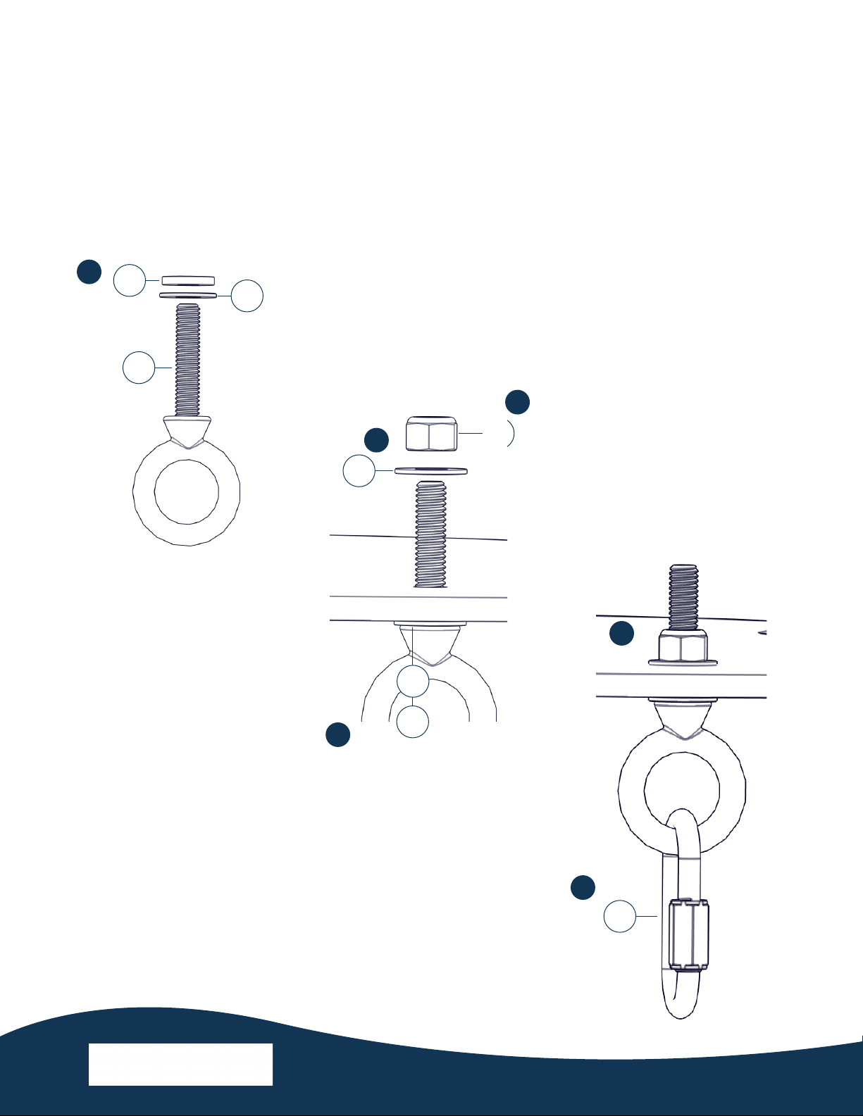
8. Fit a at washer (S) and then the sealing washer (T) onto the eye bolt (Q).
9. From the tank interior, insert the eye bolt (Q) with washers (S, T) through the 3/8” hole.
10. From the tank exterior, t a second at washer (S) onto the eye bolt.
11. Fasten the 5/16” nylon locknut (R) to the eye bolt.
12. Tighten the locknut until snug, being careful not to damage the sealing washer.
13. Attach the top connecting link (H) to the eye bolt.
R
TS
Q
8
Steel tank roof
S
T
S
9
10
11
Steel tank roof
H
12
13
Back to Contents

PM-100 PIPE MOUNT MANUAL 9
MOUNT ASSEMBLY
With multiple options in both the upper and lower mount assemblies, the PM-100 allows for versatile adjust-
ment of the unit’s position and angle within the tank.
Upper Mount Base Installation
1. Install the upper mount base (A) as desired within the tank (hardware not included).
2. Insert the 1/2”-13 x 1/4” shoulder screw (E) as specied below for either vertical or horizontal mounting.
3. Fasten with a serrated ange nut (F).
Hole location and dimensions for the upper mount base (A).
E
Vertical mounting option
Horizontal mounting option
F
A
Back to Contents
Inhaltsverzeichnis
Andere Kasco Wassersystem Handbücher


Beliebte Wassersystem Handbücher anderer Marken

Spirotech
Spirotech SPIROVENT SUPERIOR S250 Bedienungsanleitung

Culligan
Culligan Aqua-Cleer Aqua-Cleer Advanced Drinking Water... Bedienungsanleitung

A.O. Smith
A.O. Smith Dura-Max AJH - 1000A - P Bedienungsanleitung

Microline
Microline T.F.C.-4 Handbuch

Eureka Forbes
Eureka Forbes Aquaguard Select Bedienungsanleitung

Cetetherm
Cetetherm AquaEfficiency Bedienungsanleitung


