
KWM Gutterman IronMan Half-Round G2 Betriebsanleitung

OPERATING AND MAINTENANCE
TROUBLESHOOTING GUIDE
Half Round G2
Half Round G2

1
In purchasing a KWM Gutterman Inc. gutter-forming machine, you are welcomed to the growing
group of people who recognize quality and precision. KWM is proud of our modern facility and
highly trained personnel that allow KWM Gutterman Inc. to manufacture the very best roll-forming
equipment.
The operating and maintenance guide explains the features of your new KWM Gutterman Inc. gutter
machine. Please read it and follow the instructions carefully.
As the manufacturer of your roll-forming machine, KWM wants you to be completely satisfied with
your purchase. The maintenance and troubleshooting guide is designed to help answer most questions
or concerns on your roll-forming machine. A copy of our warranty is included in our maintenance
guide.
“Manufacturing the Best, Built to Stand the Test”
Please visit us at www.kwmgutterman.com for product information.
Our family business will only succeed by making you, our customer, our top priority! We are only a
phone call or a click away.
1- 888-729-4290
Thank you for your purchase!
At Your Service, We Remain.
Kenneth W. Minor Sr.
Keith W. Minor Sr.

2
TABLE OF CONTENTS
SECTION PAGE #
pg. 4
pg. 5-6
pg. 7-9
pg. 10-11
pg. 12
pg. 13
pg. 14
pg. 14-16
pg. 17
pg. 18
pg. 19
pg. 20
1.
Machine Specifications
2.
Safety and General Maintenance
3.
Electrical System and Control Locations
4.
Spool Upright Supports
5.
Entrance Guide System
6.
Gutter Talk
7.
Daily Operation
8.
Adjusting Straightness of Gutter
9.
Adjusting Width of Gutter
10.
Guillotine and Face Plate Assembly
11.
Troubleshooting
12.
Gutter Profile
3

4
SECTION 1
HALF ROUND GUTTER MACHINE SPECIFICATIONS
POWER:
-
1.5 HP, FAN COOLED (T.E.F.C.) MOTOR
-
SINGLE PHASE
- 110V
-
18 AMP
DIMENSIONS:
-
LENGTH 162”
(411.50 cm)
-
HEIGHT 51”
(129.5 cm)
WEIGHT:
DRIVE:
SHEAR
SPEED:
CONTROLS:
-
WIDTH 34.5”(87.6 cm)
-
APPROX. 2000 LBS. (907.2 kg)
-
TOP AND BOTTOM STEEL/ALUMINUM/POLYURETHANE ROLLERS
-
VIA CHAINS & SPROCKETS
-
FRONT PULL GUILLOTINE STYLE SHEAR
-
APPROXIMATELY 35’ PER MINUTE
-
ENTRANCE END
oEMERGENCY STOP
oJOG PUSH BUTTON
-
EXIT END
oSTOP BUTTON
oFORWARD & REVERSE SWITCH
oRUN & JOG SWITCH
oSTART BUTTON
RECOMMEND MATERIALS:
- PAINTED STEEL
ALUMINUM STEEL
TERNECOAT STEEL
ALUMINUM
COPPER
(MAX: 24 GAUGE)
(MAX: 24 GAUGE)
(MAX: 24 GAUGE)
(MAX: .032”)
(MAX: 16/20 OZ. 3/4” HARD)
WARNING: NO RAW OR UNCOATED MATERIAL
CALL MANUFACTURER FOR PAINT GRIP & RAW
GALVANIZED

5
SECTION 2
SAFETY AND GENERAL MAINTENANCE
1.
Read the entire manual prior to operation of this machine.
2.
Always keep covers and lids on during transportation, operation and storage. The covers are for the
operator’s safety. Not only will this protect the operator against injury, the covers protect the machine
from outside elements.
3.
Read all warning labels on machine.
4.
Disconnect the machine from power source prior to cleaning, or performing any maintenance.
5.
Perform a daily inspection for debris, loose nuts, and or bolts. With a clean machine you can expect
longer life from your machine and a better-finished product.
6.
Lubricate guillotine and chains weekly using WD40.
7.
OUTSIDE STORAGE. If machine must be stored outside on an open trailer, tarp machine loosely
providing good ventilation to prevent condensation.
8.
BE SURE the operator is trained in the operating procedures of this equipment, and all local and
national safety codes concerning the operation and the lifting of coils.
MOUNTING MACHINE
Mounting machine in truck and or trailer.
1.
When choosing a vehicle or trailer for your machine, consider the gross machine weight including
coil.
2.
Check mounting surface for its integrity and make any repairs necessary prior toinstallation.
3.
Bolt machine to the bed of the vehicle using 3/8" dia. bolts grade 5 four places. DO NOT DRAW
MACHINE DOWN TO AN UN-FLAT SURFACE. Shim as needed to insure four place mounting.
*REMOVE MACHINE FROM WOODEN SHIPPING SKID*

6
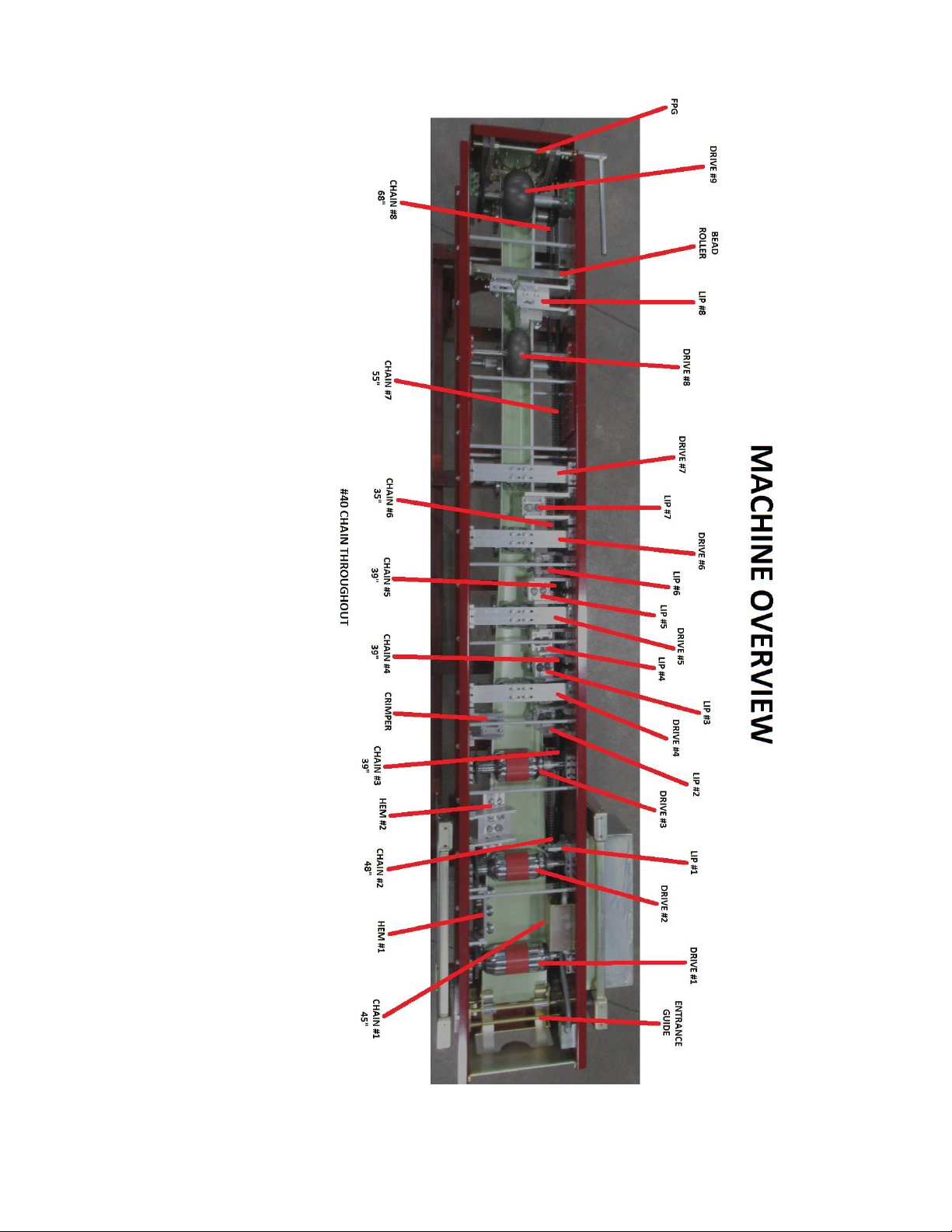
MACHINE ORIENTATION
Machine orientation is as follows: (For communication purposes in the manual.)
A.
Entrance
The entrance is where the forming process begins, where the material is fed.
B.
Exit
The exit is where the forming process is complete and the finished gutter exits the machine.
C.
Right Side
The right side of the machine is determined when facing entrance end of the machine. This is where
the LIP of the gutter is formed.
Components on Right Side:
1. Lip Side Guide Shoe (Right Shoe)
2. Lip Side Assemblies
3. Motor and Gearbox
D.
Left Side
The left side of the machine is determined when facing the entrance end. This is where the HEM of
the gutter is formed.
Components on Left Side:
6.
Hem Side Guide Shoe
7.
Hem Assemblies
8.
Bead Roller Assembly
9.
Crimper Support Assembly
E.
Center of Machine
The center of machine forms bottom section of gutter and is the drive assembly.
Components in Center of Machine:
10.
Entrance Guide Assembly
11.
Drive Assemblies
12.
FPG
7
SECTION 3
ELECTRICAL SYSTEM AND CONTROL LOCATIONS
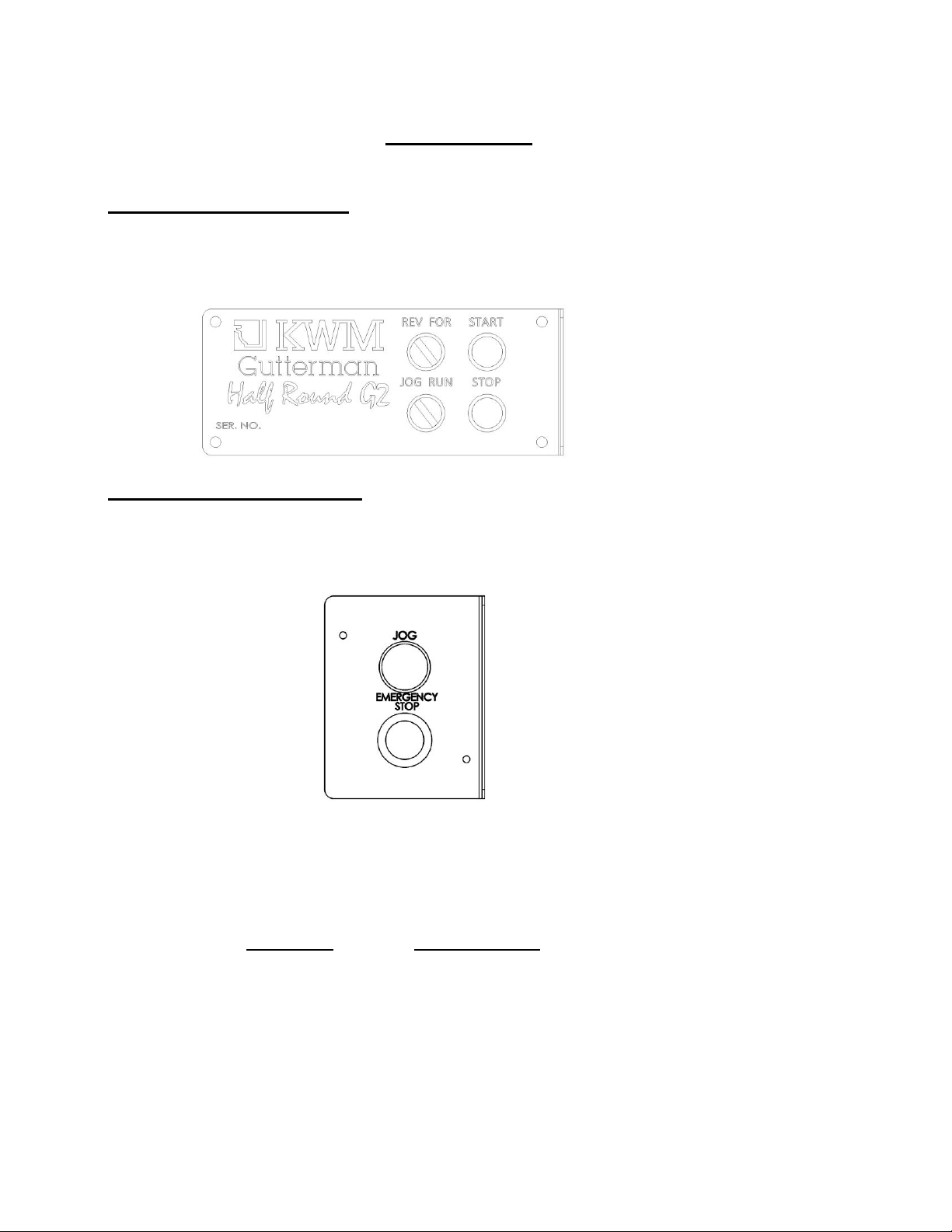
1E. MAIN OPERATORS PANEL (located on the lip side of the machine at the exit end)
The main operators panel consists of:
(2) Selector switch. (JOG/RUN & FORWARD/REVERSE)
(2) Push button. (START & STOP)
2E. ENTRY OPERATORS PANEL (located on the lip side of the machine at the entrance end)
The entry operator’s panel consists of:
(1) Jog button (push button)
(1) Emergency stop button. (power shut off)
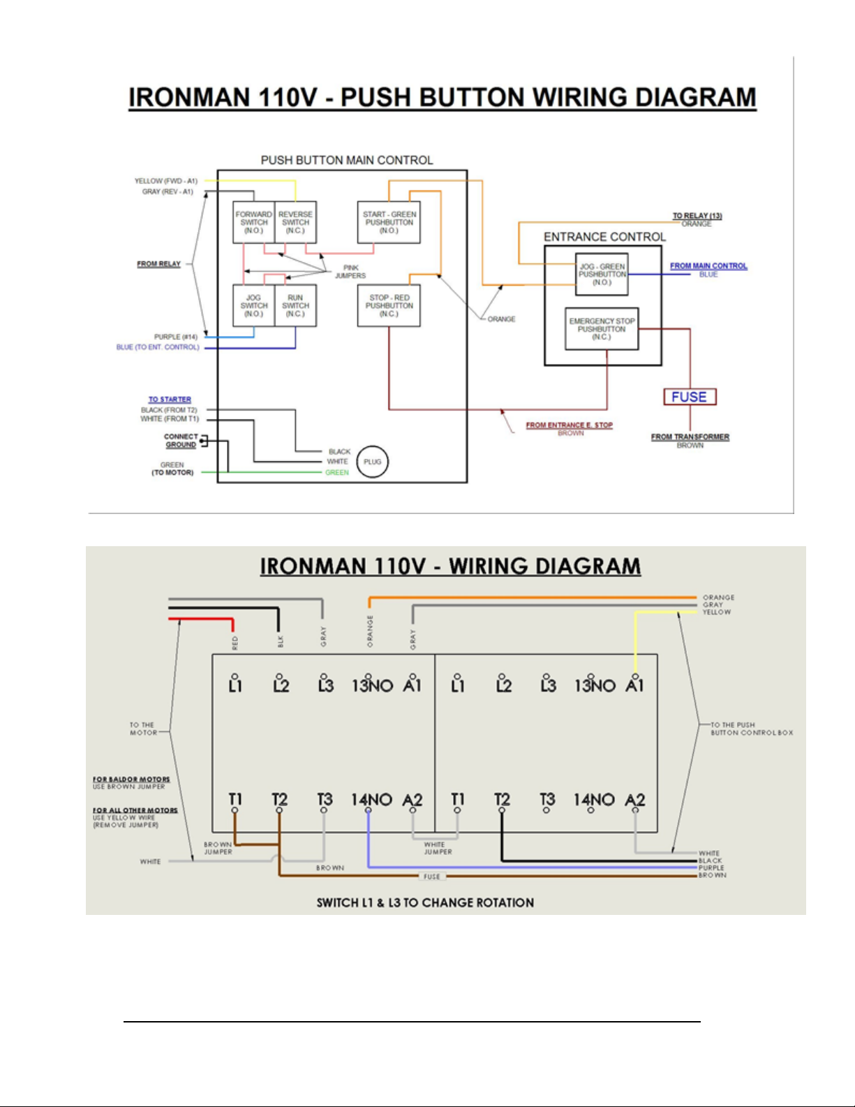
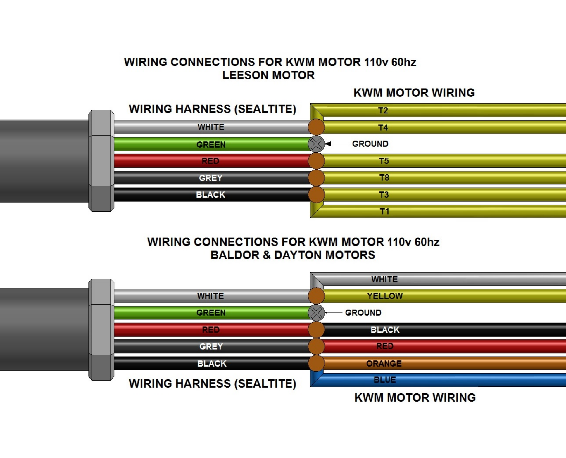
ELECTRICAL CORD REQUIREMENTS
It is important that the motor manufactures minimum wire gage be adhered to in order to maintain the
warranty on motor.
LENGTH GAGE CORD
0 –25’ 12 ga
25 –50’ 10 ga
50 –100’ 7 ga
8
Inhaltsverzeichnis


