Lectrosonics DHu Bedienungsanleitung

Quick
Start
Guide
Fill in for your records:
Serial Number:
Purchase Date:
This guide is intended to assist
with initial setup and operation of
your Lectrosonics product.
For a detailed user manual, down-
load the most current
version at:
www.lectrosonics.com
Digital Handheld
Transmitter
DHu, DHu/E01,
DHu/E01-B1C1
12 September 2022
U.S. Patent 7,225,135

LECTROSONICS, INC.2
Mechanical Assembly
The lower housing opens by rotating
it in the direction shown. After the
threads are disengaged, pull the
housing downward until it engages
the detent that holds it open.
A mic capsule is
threaded onto the body
of the transmitter in the
direction shown.
Do not overtighten it.
The threaded interface is a 1.25”
diameter opening with 28 threads
per inch and three contact rings
Microphone Capsules:
Lectrosonics oers two types of capsules. The HHC is the standard
capsule and the HHVMC is the Variable Mic Capsule which includes
adjustments for Bass, Midrange and Treble.
HHC Lectrosonics
cardioid electret
HHVMC Lectrosonics cardioid
electret with VariMic preamp
Along with these two models from Lectrosonics, a variety of dierent
capsules with a common thread and electrical interface are available
from the major microphone manufacturers.

www.lectrosonics.com 3
Do not touch the contacts between the mic capsule
and transmitter body. When necessary, the contacts
can be cleaned with a cotton swab and alcohol.
Capsule Installation
Capsules are attached with a right-hand thread.
To remove the windscreen from the mic capsule,
line up the blue wrench (included with the capsule head) with the at
notches on the lower threaded area of the mic capsule.
Align ats on
the wrench
with ats on
the capsule.
Battery Installation
Close eject
lever to install
batteries
To insert batteries, close the eject lever
and insert the upper contacts rst (closest
to the mic capsule). Polarity is marked on
the label in the bottom of the battery
compartment.
The contacts are very tight to prevent the
batteries from “rattling” as the transmitter
is being handled. Pull the eject lever out-
ward to remove the batteries. The battery
tips will move outward, making them easier
to grasp.
Pull eject lever outward
to release batteries from
contacts

LECTROSONICS, INC.4
Control Panel
Six membrane switches on the control panel are used to set up the
transmitter by navigating the menus on the LCD and selecting the
desired values.
Power Button
Modulation
LEDs
Previous
Screen
UP/DOWN Buttons for
Menu Item Selection
Enter Menu and
Select Item
IR Sync Port
Programmable
switch setup button
Setup and Adjustments
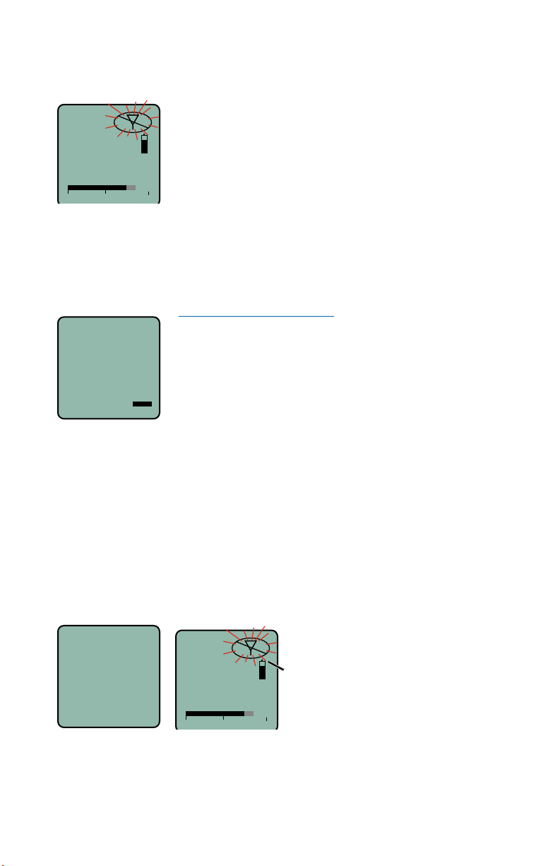
Powering On
Press and hold the Power Button until a status bar on the LCD is com-
pleted. The status bar will appear on the LCD, followed by a display of
the model, rmware version, frequency band and compatibility mode.
DHu
V1.01
Hold
for
Rf On
When you release the button, the unit will be operational with the RF
output turned ON and the Main Window displayed.
5
623.400
-40 -20 0
AThe Main Window
RF output ON
www.lectrosonics.com 5
If you release the button before the status bar is complete, the unit will
turn on in the Standby mode with the RF output turned OFF and the
antenna icon will blink.
5
623.400
-40 -20 0
AMUTE The Main Window
RF output OFF
Powering O
Press and hold the Power Button (or the side button if it is congured
for turning the power on and o) while the status bar on the LCD is
completed. The power will then be turned o. This can be done from
any menu or screen.
Powering
O . . .
NOTE: If the Power Button
is released before the status
bar has completed, the unit
will remain turned on and
the LCD will return to the
same screen or menu that
was displayed previously.
Standby Mode
A brief push of the keypad Power Button turns the unit on and places it
into a “standby” mode (not transmitting). Press the button and release
before the status bar completes. This allows the transmitter to be set
up without the risk of creating interference for other wireless systems
that are operating in the vicinity.
A notice will appear briey conrming that the RF output of the trans-
mitter is turned o, followed by the Main Window. The antenna symbol
will blink as a reminder that the RF output is turned o.
5
623.400
-40 -20 0
AMUTE Symbol blinks
when RF output
is turned OFF
Rf
Off

LECTROSONICS, INC.6
Main Menu and Setup Screen
Details
Entering the Main Menu
The LCD and keypad interface makes it easy to browse the menus and
make the selections for the setup you need. When the unit is powered
up in either the operating or the standby mode, press MENU/SEL on
the keypad to enter a menu structure on the LCD. Use the UP and
DOWN arrow buttons to select the menu item. Then press the MENU/
SEL button to enter the setup screen.
-40 -20 0
Gain
25
The prompt in the upper right corner may display one or
both arrows, depending upon what adjustment can be
made. If the changes are locked, a small padlock symbol
will appear.
Main Window Indicators
The Main Window displays on/o status, talkback or audio mute status,
standby or operating mode, operating frequency, audio level and
battery status.
DHu
545.400
-40 -20 0
MUTE
Frequency (MHz)
RF On/Off
Status
Battery status
Audio level
Audio Mute or
Talkback status
If the programmable switch function is set for Mute or Talkback, the
Main Window will indicate that the function is enabled.
www.lectrosonics.com 7
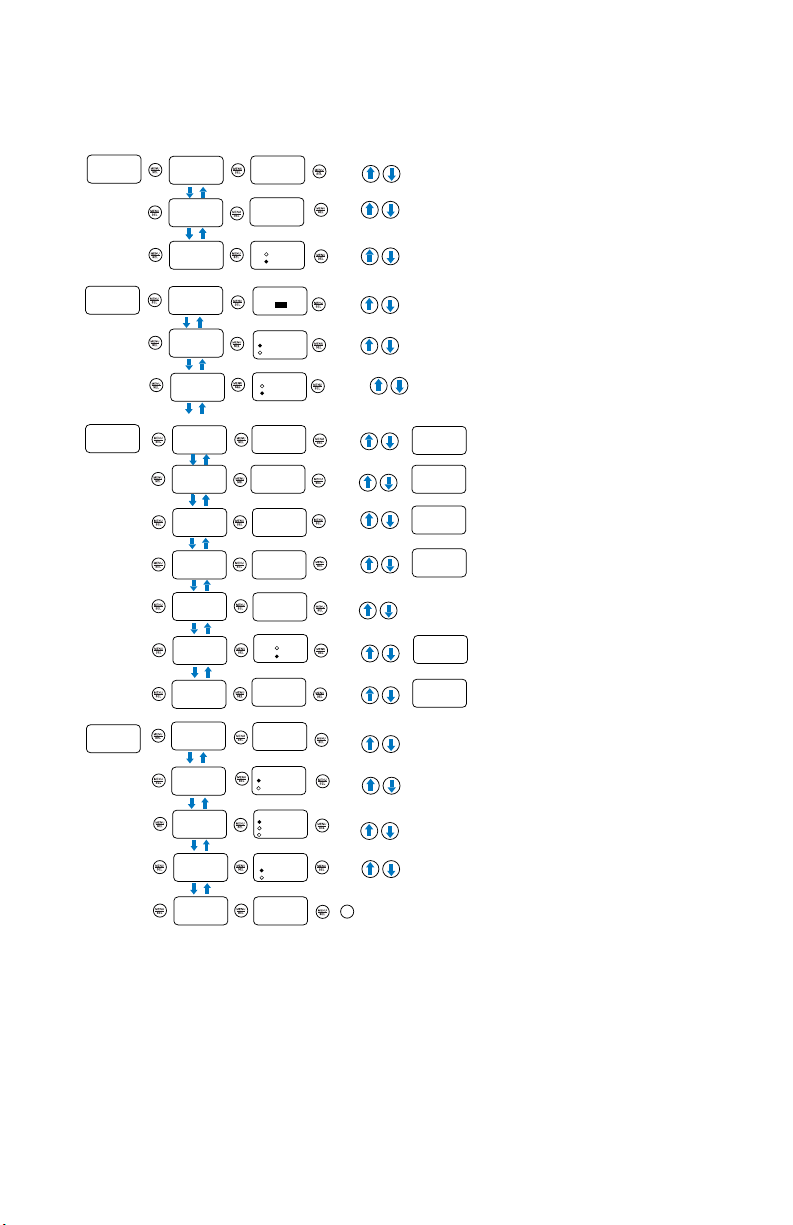
Menu Map
DHu
Main Menu Tree
Rolloff
Input Gain Gain
22
Select option with arrow buttons
to select.
Select option with arrow buttons
to select.
to select.
Rolloff
70 Hz 1
Phase Phase
Freq.
Xmit Select Freq. in mHz or kHz with arrow buttons
to select.
Freq.
470.100
RF On?
Tx Power
Select option with arrow buttons
to select.
Select level with arrow buttons
Backlit
Backlit
On
30 Seconds
5 Seconds
Select option with arrow buttons
to select.
Bat Type
Bat Type
Alk.
Lith.
Select option with arrow buttons
to select.
Setup
About
About
DHu
V1.13
/2.00
Default Default
settings
No
Yes
Select option with arrow buttons
to select.
or to go back.
to get key.
to send key.
IR&Key
Select option with arrow buttons
to select.
Send Freq
Sync --->
Send Freq
Send All Send All
Get Freq Get Freq
Get All Get All
Select option with arrow buttons
to select.
Key Type Key Type
Standard
IR
SYNC
OK
IR
SYNC
OK
IR
SYNC
OK
IR
SYNC
OK
ProgramSw
TalkBk
Select option with arrow buttons
to select.
ProgSw
|-40 |-20 +0|
Wipe Key
Make Key?
No
Yes
Select option with arrow buttons
to select. Encrytion
key
ERASED
* This menu item is
only available in
Shared key mode. Send Key
Send Key
Send --->
Select option with arrow buttons
to select. IR
SYNC
OK
RF On?
Yes
No
TxPower
25 mw
50 mW
Sync --->
Sync --->
Sync --->
Select option with arrow buttons
to select.
Select option with arrow buttons
to select.
BACK
Normal
Invert

LECTROSONICS, INC.8
Menu Item Descriptions
Input
Gain
Gain can be set, from -7 to +44, by using the and arrow buttons.
Adjusting the Input Gain
The two bicolor Modulation LEDs on the top panel provide a visual indi-
cation of the audio signal level entering the transmitter. The LEDs will
glow either red or green to indicate modulation levels as shown in the
following table.
Signal Level -20 LED -10 LED
Less than -20 dB O O
-20 dB to -10 dB Green O
-10 dB to +0 dB Green Green
+0 dB to +10 dB Red Green
Greater than +10 dB Red Red
NOTE: Full modulation is achieved at 0 dB, when the “-20” LED
first turns red. The limiter can cleanly handle peaks up to 30 dB
above this point.
It is best to go through the following procedure with the transmitter
in the standby mode so that no audio will enter the sound system or
recorder during adjustment.
1) With fresh batteries in the transmitter, power the unit on in the
standby mode (see previous section Powering On in Standby
Mode).
2) Navigate to the Gain setup screen.
-40 -20 0
Gain
25
3) Prepare the signal source. Position a microphone the way it will
be used in actual operation and have the user speak or sing at
the loudest level that occur during use, or set the output level of
the instrument or audio device to the maximum level that will be
used.

www.lectrosonics.com 9
4) Use the UP and DOWN arrow buttons to adjust the gain until the
–10 dB glows green and the –20 dB LED starts to icker red dur-
ing the loudest peaks in the audio.
5) Once the audio gain has been set, the signal can be sent through
the sound system for overall level adjustments, monitor settings,
etc.
6) If the audio output level of the receiver is too high or low, use
only the controls on the receiver to make adjustments. Always
leave the transmitter gain adjustment set according to these
instructions, and do not change it to adjust the audio output level
of the receiver.
Rollo (Low Frequency Roll-o)
The low frequency audio roll-o is adjustable to optimize performance
for ambient noise conditions or personal preference.
Low frequency audio content may be desirable or distracting, so the
point at which the roll-o takes place can be set to 20, 35, 50, 70, 100,
120 or 150 Hz.
Rolloff
70 Hz
Phase (Selecting Audio Polarity)
This setting allows for conguration for use with certain microphones,
or for setting custom parameters.
Phase
Normal
Invert
Xmit
Setting Frequency
Frequency (mHz and kHz) in can be set by using the MENU/SEL
button to choose mHz or kHz and the UP and DOWN arrows to adjust
frequency.

LECTROSONICS, INC.10
Tuning Groups
Tuning groups can be received via IR (Infared) port sync from a receiver.
The group frequencies are set by the receiver. The group names will be
displayed at the bottom of the screen as Grp x, Grp w, Grp v, or Grp u.
Use the MENU/SEL button to toggle between options and the UP and
DOWN arrow buttons to adjust.
RF On?
Turn Rf o to preserve battery power while setting other transmit-
ter functions. Turn it back on to begin transmitting.. Use the UP and
DOWN arrow buttons to toggle and MENU/SEL to save.
TxPower
Allows the transmitter output power to be set as 25 or 50 mW. Use the
UP and DOWN arrow buttons to scroll and MENU/SEL to save.
Andere Handbücher für DHu
4
Dieses Handbuch passt für folgende Modelle
2
Inhaltsverzeichnis
Andere Lectrosonics Mikrofon Handbücher


Beliebte Mikrofon Handbücher anderer Marken

IK Multimedia
IK Multimedia iRig Stream MIC PRO Bedienungsanleitung

DAPAudio
DAPAudio RM-101 Bedienungsanleitung

AKG
AKG CHM 21 Bedienungsanleitung

Sennheiser
Sennheiser evolution wireless series EM 100 Bedienungsanleitung

Sony
Sony C-48 Bedienungsanleitung

GIGAMEDIA
GIGAMEDIA GGM PAMICUHFG Bedienungsanleitung


