Lockwood Digital Deadbolt Bedienungsanleitung

USER GUIDE
Lockwood Digital Deadbolt
DIGITAL DEADBOLT


3
Warnings _______________________________________________________________________________________________4
Introduction_____________________________________________________________________________________________4
Installation _______________________________________________________________________________________________
Components and Tools _________________________________________________________________________________5
Prepare Lock for Installation_____________________________________________________________________________6
Install Lock ___________________________________________________________________________________________7
Programming_____________________________________________________________________________________________
Programming Features-Menu Keys-Definitions _____________________________________________________________9
Components and Tools ________________________________________________________________________________10
Definitions __________________________________________________________________________________________10
Operation___________________________________________________________________________________________11
Feature Programming Through Menu Mode Using Master PIN code ___________________________________________13
Miscellaneous Information__________________________________________________________________________________
Hardware Troubleshooting _____________________________________________________________________________14
Programming Troubleshooting__________________________________________________________________________15
Reset Lock to Factory Default ___________________________________________________________________________16
PIN Code Management Sample Sheet ____________________________________________________________________17
Replace/install Cylinder ________________________________________________________________________________18
Table of Contents

4
The Lockwood Stand-alone Digital Deadbolt Lock combines a robust lockset with a contemporary electronic
aesthetic. Users benefit from a touch keypad that makes day-to-day access effortless. Up to twenty codes can be
distributed amongst users to allow a keyless solution for accessing secure doors. Lockwood Digital Deadbolt is
engineered for quick and easy installation and fits in place of a standard deadbolt prep.
WARNING: Changes or modifications to this device not expressly approved by ASSA ABLOY could void the user’s
authority to operate the equipment.
CAUTION: Changes or modifications to this unit not expressly approved by the party responsible for compliance
could void the user’s authority to operate the equipment.
IMPORTANT: The accuracy of the door preparation is critical for the proper functioning and security of this product.
Misalignment can cause premature wear and a lessening of security. The Lockwood Digital Deadbolt should only be
serviced by a qualified technician.
Finish Care: This lockset is designed to provide the highest standard of product quality and performance.
Care should be taken to ensure a long-lasting finish. When cleaning is required use a soft, damp cloth. Using lacquer
thinner, caustic soaps, abrasive cleaners or polishes could damage the coating and result in tarnishing.
This lock may not be used on moving doors, i.e., Cars, Trains or similar applications. The lock is designed for
residential and commercial applications only and door sizes between 32-50mm. We highly recommend that a
secondary entrance is required in the unlikely event of total failure. This lock may not be used on fire doors.
Introduction
Warnings

5
Inside
Escutcheon 4 AA Alkaline
Batteries
(2) Through
bolts Keys
Bolt
Strike Plate
(4) Bolt & Strike Plate
Mounting Screws
(3) Inside Escutcheon
Mounting screws
Inside Mounting Plate
with Gasket
(back of Inside Escutcheon)
Battery Cover
Outside
Escutcheon
Door Prep Lock Installation
• 54mm hole saw • #2 Phillips screwdriver
• 25.4mm spade bit
• 2.5mm drill bit
• Chisel & hammer
Components and tools
INSTALLATION
• Installation & Programming Guide • Inside Mounting Plate • Strike Plate
• Outside Escutcheon • Battery Cover • Screw Pack
• 4 AA Alkaline Batteries • Keys • Plastic Gaskets
• Inside Escutcheon • Bolt • Rubber Gaskets
Included in the box...
Parts Illustrations
Tools Needed

6
Battery Cover
Inside Escutcheon
Inside Escutcheon & Mounting Plate
(with gasket)
Outside Escutcheon
1
2
3
Figure 3B
Figure 3A
B. Bolt
NOTE: Bolt ships with backset in 60mm
position. If required, press small black button
on underside of bolt and pull to extend to
70mm backset position (Fig. 3B).
The lock is packed representative of how it will install on the
door.
Before installing the lock on the door:
A. Inside escutcheon
1. Loosen the screw (Phillips #2) holding the battery cover.
(The screw remains attached to battery cover)
2. Slide the battery cover up and out (note the two tabs at
bottom of battery cover).
3. Remove the inside mounting plate (with gasket) from the
back (door side) of the inside escutcheon.
a. Ensure that gasket on both Outside
Escutcheon and Inside Mounting
Plate (Figure 3A) is properly fitted.
Use either Rubber gaskets for doors
37-50mm thick or Plastic gaskets
for doors 32mm-36mm thick.
C. The outside escutcheon (with gasket remains assembled).
Unpack the Lock
Prepare lock for installation

7
Figure 3A
(2) M4 x 25.4mm
[8-32 x 1"]
Flat Head
Combination Screws
(2) M4 x 25.4mm
[8-32 x 1”]
Flat Head
Combination Screws
1
2
Figure 4A
“Tongue”
Inside of Door
Figure 4B
Figure 3B
3. Install outside escutcheon.
As you position the outside escutcheon, route the
cable through 54mm diameter hole (Figure 3A).
5. Secure both assemblies using (2)
M6 x 54mm pan head machine
screws (Fig. 4B), making sure that
outside escutcheon is vertically
aligned. Hand-tighten until snug.
Do not over-tighten
1. Install bolt in door.
NOTE: The bolt must be in a retracted (unlocked) position
when installing the lockset.
Attach with (2) M4 x 25.4mm screws supplied.
2. Install strike on the door frame, making sure to allow for the
bolt to be centred in the strike.
4. Holding the outside escutcheon flush to the door,
positioning the inside mounting plate by first routing the
cable and connector through the mounting plate’s 1/2” hole,
then inserting the mounting plate “tongue” into the bottom
slot of the outside escutcheon. See (Fig. 4A).
NOTE: Cable goes under bolt (see Fig. 3B).
Install Lock

8
Figure 6B
Figure 7
Figure 6A
Figure 9
Figure 8
CAUTION:
Use care when assembling to ensure that the cable lies against
the back recessed area of the inside escutcheon (Fig. 6A).
Position and bend cable, using the harness clips as shown in Fig.
6A to prevent binding when installing the escutcheon over the
mounting plate.
6. Attach cable assembly to the inside escutcheon PC board by
lining up notches on top of cable connector to slots on PCB
connector (Fig. 6B).
NOTE: Connector should be pressed in firmly using thumbs until
completely seated.
Proper position is indicated by arrows on PCB as in Fig. 6A & 6B.
7. Install inside escutcheon on inside mounting plate. Note the
horizontal orientation of the tail - piece (Fig. 7) as you insert
the inside escutcheon (thumbturn should be vertical).
8. Install and secure using (3) M4 x 8mm pan head screws
through the inside escutcheon into the mounting plate (Fig. 8).
IMPORTANT: Before installing the batteries, test
the mechanical operation of the lock by using both
thumbturn and the key. The movement of the bolt
should be smooth and unobstructed. If operation
is not smooth, review the previous steps to ensure
proper installation.
NOTE: The bolt must be in a retracted (unlocked) position prior
to installing the batteries.
9. Insert four (4) AA alkaline batteries. The lock responds with
a series of beeps, and a quick flash of all keypad LEDs. When
activating the lock for the first time, the lock will adjust for proper
handing.
NOTE: Refer to programming instructions prior to completion of
step 10.
10. Install battery cover and tighten Phillips head screw.

9
Phillips Head Screw
Alkaline Batteries
4 AA Type
Thumbturn
Status Indicator
Battery Cover
Speaker Hole
Lockout Mode
Cylinder
Low Battery
Indicator
Numbers
Touchscreen P Key
(Return to Previous)
Privacy Mode Button
PROGRAMMING
Programming Features-Menus-Keys-Definitions ________________________________________9
Operation________________________________________________________________________11
Programming Features - Menus - Keys - Definitions
Outside Inside
Menu and Icons Used in This Guide
Click the indicated number Enter Master PIN code (4-8 digits in length).
Press the on the keypad to Enter or Accept entry.
Enter User PIN. Can be 4-8 digits in length.
Press the Star key on the keypad to enter the Menu
mode.
Manage up to 20 user pin codes. Pin code
Management Sample Sheet on page 16 of
this booklet.

10
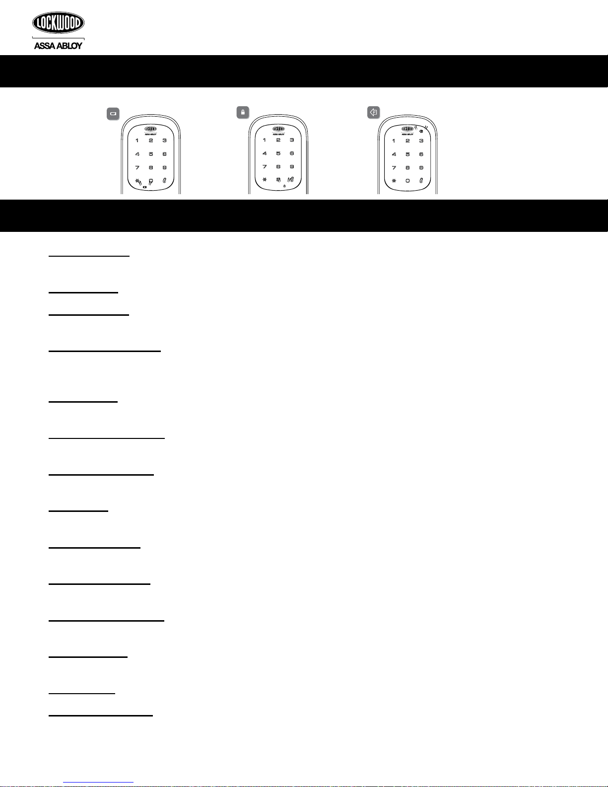
Low Battery Warning All Code Lockout Mode Return to previous step
Master PIN Code: The Master PIN code is used for programming and for feature settings. It must be registered prior
to programming the lock. The Master code will not operate (unlock/lock) the lock (Main menu selection #1).
User PIN Code: The User code operates the lock. Maximum number of user codes is 20 (Main menu selection #2).
Visitor Pin Code: Visitor code can be valid from 3-336 hours(2 weeks). Allowing the visitor a four digit pin code for
a limited set time. (Main menu selection #5)
All Code Lockout Mode: This feature is enabled by the Master code. When enabled, it restricts all user (except
Master) PIN code access. When attempting to enter a code while the unit is in Lockout, the red locked padlock will
appear on the screen. (Main menu selection #6).
Volume Mode: The volume setting for PIN code verification is set to High (1) by default. Otherwise it can be set to
Silent (3) (Main menu selection #4).
Automatic Re-lock Time: After a successful code entry and the unit unlocks, you can set your lock to automatically
re-lock after (10) seconds (Main menu selection #3*1).
Inside Indicator Light: Shows active status (Locked) of lock and can be enable or disabled in the Advanced Lock
Settings (Main Menu selection #3) (Main menu selection #3*2).
Low Battery: When battery power is low, the low battery icon will begin flashing. If battery power is completely lost,
use the key override.
One Touch Locking: When the latch is retracted, touching the keypad will extend the bolt (during Automatic
Re-lock duration or when Automatic Re-lock is disabled).
Privacy Mode Button: Pressing and holding the Privacy button (found below thumb turn) for a duration of four beeps
deactivates the keypad, and because it is set from the inside, provides a secure lock for the convenience of the occupant(s).
Wrong Code Entry Limit: After five (5) unsuccessful attempts at entering a valid PIN code the unit will shut down
and not allow operation.
Shutdown time: The unit will shutdown for a default of one hundred and eighty (180) seconds and not allow operation
after the wrong code entry limit has been met. When the unit is in Shutdown, the red locking symbol will be flashing.
Tamper Alert: Audible alarm sounds if attempting to forcibly remove outside lock from door.
Cryptic code function: Prevent others from identifying your pin code during access, the cryptic code function
confuses the onlooker but at the same time allows you to still gain entry. You are able to enter any random
amounts of digits before you enter your actual code, followed by your real pin code. e.g. if your code is 1234 enter
23456721234. You are also able to enter your pin first followed by any random numbers. e.g. 12342765432
Definitions
Components and tools
Andere Handbücher für Digital Deadbolt
1
Inhaltsverzeichnis
Andere Lockwood Sperren Handbücher

Lockwood
Lockwood PADDE TRIMEC 200 Series Bedienungsanleitung

Lockwood
Lockwood Nexion Classic Bedienungsanleitung

Lockwood
Lockwood PADDE TRIMEC PRE-LOAD ES9000 Series Bedienungsanleitung

Lockwood
Lockwood ST8011SSS Bedienungsanleitung

Lockwood
Lockwood ES150 Series Bedienungsanleitung

Lockwood
Lockwood 3578 Series Bedienungsanleitung

Lockwood
Lockwood ASSA ABLOY Induro Bedienungsanleitung


