
LSM Doran 360M Bedienungsanleitung

360M
READ THE ENTIRE MANUAL CAREFULLY
BEFORE USING THIS PRODUCT.
2007 Doran Mfg. LLC
All rights reserved.
BE SURE TO READ THE INSTALLATION INSTRUCTIONS ON PAGES
4 THRU 7 BEFORE INSTALLING THE VALVE SENSORS.
Please log serial numbers from sensors here!
F(front) sensor's last three digits of serial number __ __ __.
R(rear) sensor's last three digits of serial number __ __ __.
Last three digits
The DORAN 360M is designed solely to monitor tire pressure. It is not designed to provide
warning of a potential or actual tire blowout.
The National Highway and Traffic Safety Administration considers a tire flat when the
pressure is 25% below the tire manufacturers recommended operating pressure.
USER MANUAL

I. Introduction to the DORAN 360M----------------------------------------------------------------------------------- 1
II. Installation Instructions ------------------------------------------------------------------------------------------------2
A. Installing the Monitor---------------------------------------------------------------------------------------------2
B. Installing the Sensors--------------------------------------------------------------------------------------------3
1. Outside the wheel Installation-------------------------------------------------------------------------3
2. In-Wheel Installation------------------------------------------------------------------------------------ 4
3. Removal of tire from rim w/ installed Sensors----------------------------------------------------6
III. Function and Operation-----------------------------------------------------------------------------------------------7
A. Normal Operation-------------------------------------------------------------------------------------------------7
B. Alert Mode ----------------------------------------------------------------------------------------------------------8
1. First Stage Alarm ----------------------------------------------------------------------------------------8
2. Second Stage Alarm-------------------------------------------------------------------------------------9
C. Programming Modes-------------------------------------------------------------------------------------------10
1. Programming a Sensor--------------------------------------------------------------------------------10
2. Programming the Baseline Air Pressure---------------------------------------------------------12
3. Sensor Deletion Programming----------------------------------------------------------------------13
4. Pressure Unit Programming-------------------------------------------------------------------------13
5. End Mode-------------------------------------------------------------------------------------------------14
IV. Frequently Asked Questions and Answers---------------------------------------------------------------------15
V. Important Tips ---------------------------------------------------------------------------------------------------------16
VI. Specifications ---------------------------------------------------------------------------------------------------------17
VII. Warranty---------------------------------------------------------------------------------------------------------------18
Table of Contents
Introduction
The DORAN 360M is a full-time direct tire pressure monitoring system, which includes one
monitor and two sensors. The system is a tire pressure monitoring system that displays
tire pressure. It is not designed to provide warning of a potential or actual tire blowout.
The sensor is screwed on the valve stem either internally or externally to sense the pressure of
the tire and transmit the data to the monitor through Radio Frequency ( RF ) technology. After
the monitor receives the data it will be displayed on the screen. The monitor will issue different
alarms based on the programmed pressures. When used properly, the DORAN 360M will inform
the driver of the tire pressures on the vehicle to provide the operator an opportunity to make any
necessary adjustments to the air pressure before a serious problem occurs. Because the system
uses RF technology and interference could occur with the RF transmission, no guarantee of signal
reception can be made. However, when a signal is received, the system will provide an alert of
low pressure.
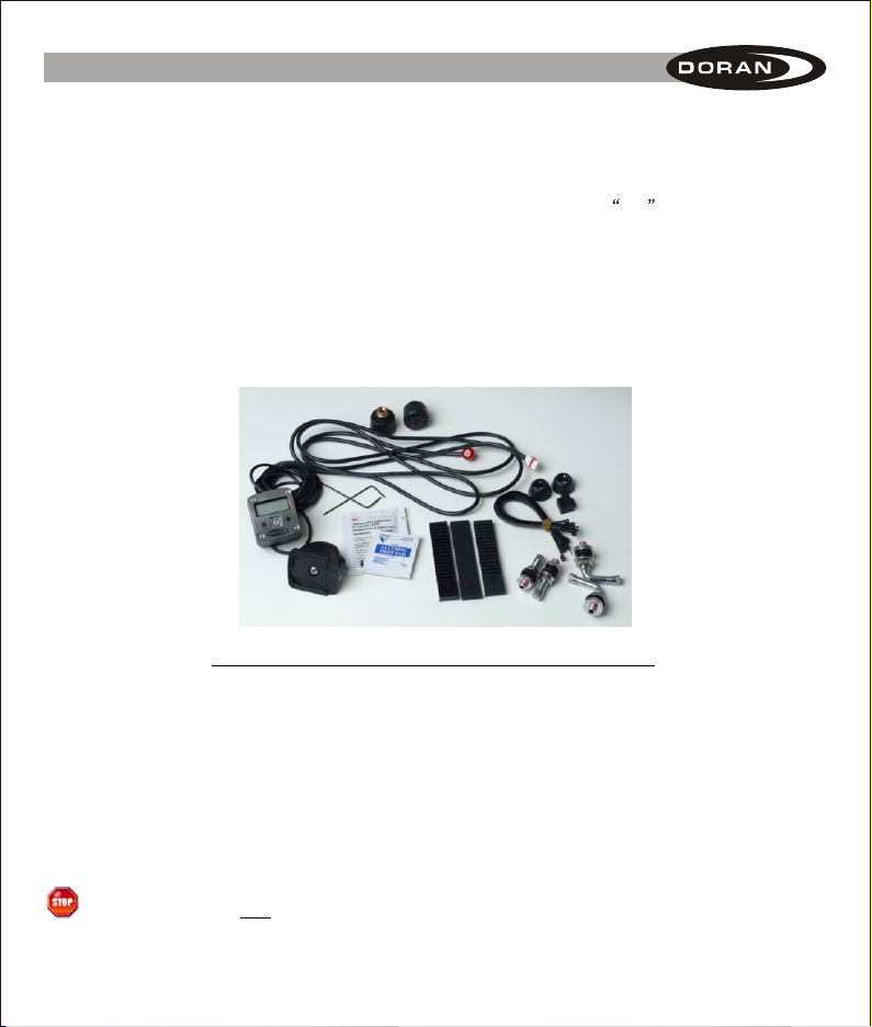
The DORAN 360M comes with the following components:
(1) - Monitor w/ attached power cord (1) - External warning lamp
(1) - Handlebar attachment bracket w/ screws (2) - Sensors
(3) - Sizing straps for handlebar sizing (1) - Velcro attachment pads
(2) - Straight replacement valve stems (2) - 90-degree replacement valve stems
(10) - Nylon wire ties (2) - Sensor locks
(2) - Wrenches for sensor Locks (2) - Alcohol Prep Pads
(1) - 3M adhesion Promoter Pad
If you are missing any of these components, DO NOT proceed with installation.
Contact the manufacturer for any missing or replacement parts.
1
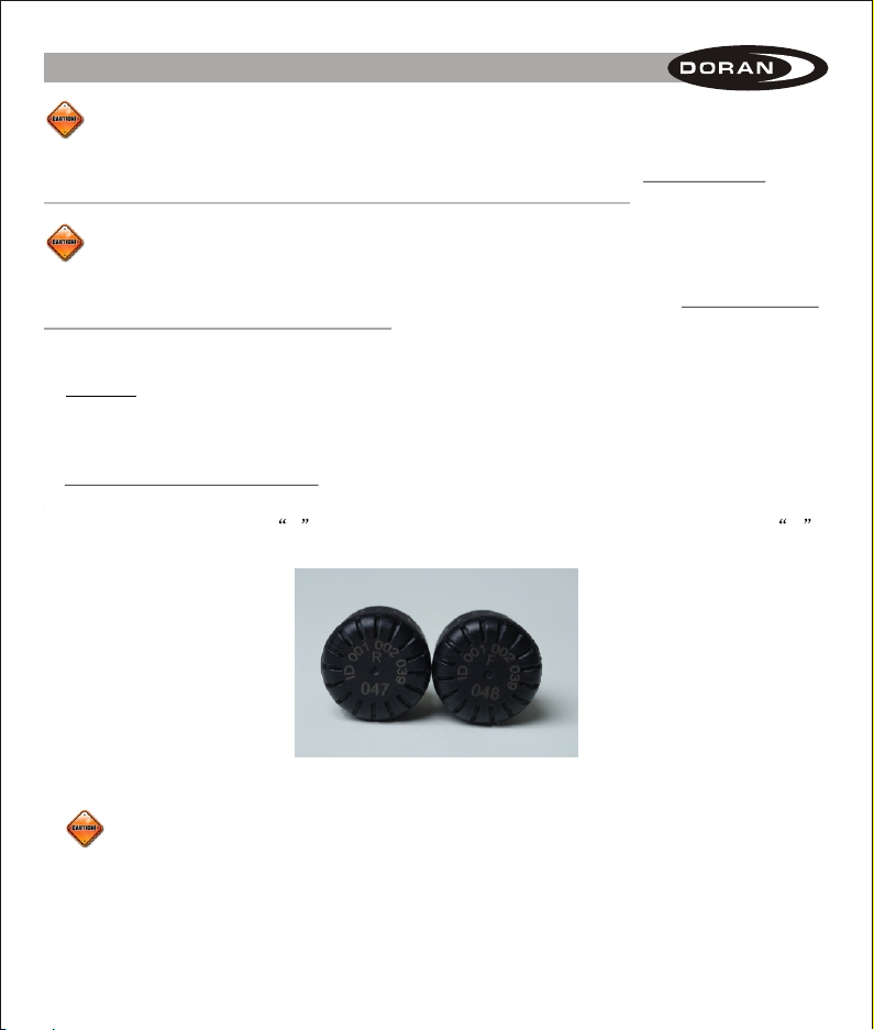
IMPORTANT: BEFORE GOING ANY FURTHER, PLEASE WRITE DOWN THE LAST THREE
DIGITS OF THE SERIAL NUMBERS OF EACH SENSOR ON THE FRONT PAGE OF THIS
MANUAL FOR YOUR FUTURE REFERENCE.
READ ALL OF THESE INSTRUCTIONS BEFORE INSTALLATION
Introduction
Installation
When you receive your new system:
Sensor IDs are already preprogrammed to your monitor
Baseline pressures are already set to 35 psi
Attach monitor and sensors per instructions.
Read all instructions carefully for complete system operations.
A. Monitor
We recommend that the monitor be placed in front of and in clear view of the driver at
all times.
The installation of the DORAN 360M is quite easy!
1. Locate a mounting position of your choice and attach the monitor to the vehicle. Included in
your kit is a handle bar mounting bracket and double-sided adhesive pads that you can use to
attach the monitor.
Option: If you prefer your monitor to be less noticeable, you may want to use the remote LED
warning light, which will also provide a low-pressure warning. This can be attached to
the mirror, fairing, or other part of the motorcycle. When a warning is received, the
light will blink and you can retrieve the pressures by looking at the monitor when you
stop to check the tires.
2. Connect the ( ), positive wire to a 12-volt positive connection, and the (black) negative wire
to a good ground connection. The monitor is fused internally so you will not need to install a
fuse in-line. You may want to connect the positive wire to a switched connection so the unit
is only operational when the vehicle is running. This will save battery power when the vehicle
is not being used, but with this method, alerts that are transmitted while the monitor is
turned off will not be updated until the ignition switch is turned on. It could take up to
six minutes for the sensors to report in to the monitor for present updates.
red
2
When the monitor is connected to a non-switched circuit the monitor will draw a very small
amount of current all the time. Leaving the monitor turned on a month at a time without charging
the battery should not cause a complete discharge of the battery. However, periodic checks
should still occur to make sure the battery continues to maintain a charge.
Conduct a regular visual inspection of the motorcycle's tires. The sensors are not a
substitute for proper tire maintenance and it is the user's responsibility to maintain proper
amounts of tire pressure and respond accordingly to warnings and alerts. Low tire pressure
is not the only problem associated with tires. Therefore, symptoms such as bulges, uneven tread,
abnormal noise, etc. should immediately be brought to the attention of a professional.
B. Sensors
REPLACING RUBBER VALVE STEMS WITH METAL VALVE STEMS IS HIGHLY
RECOMMENDED FOR EITHER INSTALLATION METHOD.
1. Outside the Wheel Installation
This is the only method that can be used for wheels using an inner tube.
a. Screw the sensor labeled F onto the Front tire valve-stem. Screw the sensor labeled R
to the Rear tire valve stem.
b. Check for clearance between the sensor and components around the wheel location
for any interference with the sensor.
3
Installation
c. If the baseline pressures that you want to monitor are 35 psi then the installation is complete
(you can then proceed to Section III to learn how the system functions).
d. To Change the baseline air pressures please see Baseline Air Pressure Programming on
page 12 of this manual. We recommend that you set the baseline pressure at the same
pressure as your recommended Manufacturers Operating Tire Pressures.
The National Highway and Traffic Safety Administration considers a tire flat when the pressure
is 25% below the tire manufacturers' recommended operating pressure.
e. Check the connection between the valve stem and the sensor for leaks. To check the
connection, use a soapy solution and watch for bubbles to appear around the sensor
connection.
2. In The Wheel Installation
If you are running tubeless tires and want your sensors on the inside of your tires you should
have a service center install the system, including the appropriate valve stems included in your
TPMS kit for your application.
NOTE: Before you take your system to a service center for installation, follow the
instructions for the Outside the Wheel installation to ensure functionality of the system. You can
then take the sensors off the outside of the tire and schedule your visit to the service center for
inside-the-wheel installation.
egree valve stems are included for the proper application
to your motorcycle. Use the appropriate stem for your needs.
d. Be sure to use the proper seal on the inside of the wheel. Install the metal washer to the
Outside of the wheel along with a nut to hold the valve stem in place. Refer to Figure 2-1
Failure to follow these instructions could result in tire or sensor damage.
Check for proper operation of the sensor BEFORE you install it inside the wheel.
a. Remove the first wheel from the motorcycle.
b. Remove the tire and the original valve stem from the wheel.
c. Two straight valve stems and two 90-d
.
4
Installation
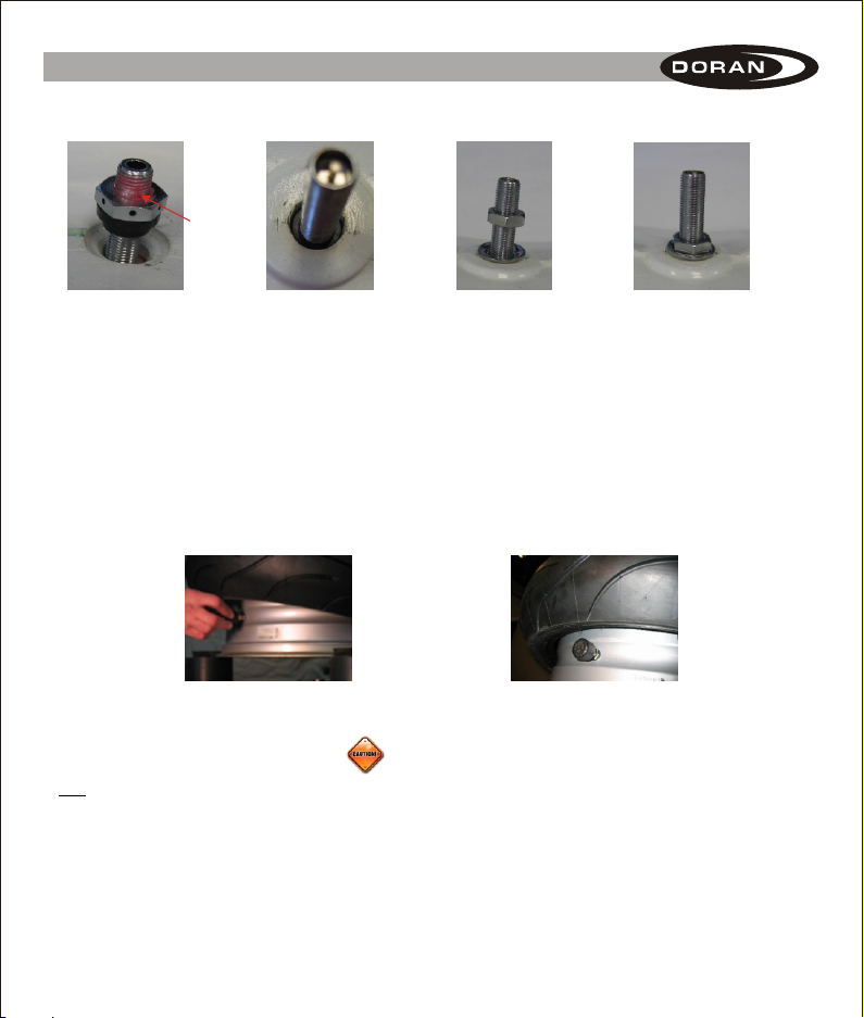
Introduction
Thread
locking
material
Step-Seal
used for hole
that is larger
than the Valve
stem
Seal and stem
centered in the
hole for Valve
stem
Metal washer
inverted to allow
the washer to
keep the valve
stem centered
Nut tightened to
secure valve stem
to wheel
Figure 2-1
e. Install the bottom tire bead over on the rim (see Figure 2-2 and 2-3).
Figure 2-2 Figure 2-3
f. Install the sensor to the valve stem. The sensor should be tightened only by hand,
not with a tool. Use a firm grip and tighten the sensor. It should stop when the threads are
fully engaged. A thread locking material has been added to the internal threaded portion of the
stem that will be on the inside of the wheel (see Figure 2-1). Install the correct sensor into the
appropriate wheel (front or rear). The sensor will bind to the added Thread Locking material
and as a result, the vibration of driving will not allow the sensor to become loose in the tire.
g. Carefully pull the bottom bead over the sensor so that the sensor isn't damaged.
(See Figure 2-4)
5

h. Start the top tire bead ahead of the sensor in a clockwise position (e.g., sensor at the 12
o'clock position and the start of the tire bead at the 9 o'clock position) so when you have
finished mounting the tire you will not be in the area of the sensor which could damage it
if it gets caught up in the tire mounting tool. (See Figure 2-5)
Introduction
Figure 2-4
Valve stem
at 12 o'clock
position
Bead started at 9
o'clock position
Figure 2-5
i. Fill the tire with the proper baseline air pressure and then have your tire properly balanced and
re-installed on the motorcycle.
j. Repeat steps a. through i. for tire # 2.
After completion of the above steps for each sensor, you will be able to monitor your tire pressure.
If the baseline pressure needs to be adjusted from the pre-programmed 35-psi setting see page
12 of this manual for the proper method of adjustment.
A. Remove wheel assembly from motorcycle and deflate the air
from the wheel.
B. Start with the valve stem at 12 o'clock and the tool to
remove the top bead of the tire at 3 o'clock.
C. Start to remove the top bead, but you must stop the tool
before it reaches the 12 o'clock position. The tool could break
the sensor if it comes in contact with it. The top bead should
now be free of the wheel.
D. Physically take the bottom bead of the tire and move it to the
topside of the sensor. This will allow the bead to be removed
without binding on the sensor (see Figure 3-2).
Figure 3-2
3. Removal of tire from rim when sensors are already installed
6
Insert the tire tool at the 3 o'clock position to remove the bottom bead of the tire. Care should be
taken to insure that the bead is free of the sensor during removal.

7
When the monitor is turned on, it will display three dashes (---)
(see Figure 4-1) for both wheel locations, if you have installed
the optional exterior stick-on warning light, you will see the red
light flash three times and then pause. This will repeat until the
sensor has checked in and is recognized by the monitor. until
the monitor has received a signal from each wheel sensor.
1. Display - The monitor will display on (see Figure 4-2) when:
The sensors have checked in with the monitor and the signals are received and the air
pressures are within the programmed range, which is within the 12.5% range of the
baseline air pressure (set at 35 psi for Front and Rear at the factory).
If the air pressure is not within the 12.5% range of the baseline pressure a warning will occur
(See Alert mode this Section B).
It could take up to six (6) minutes for the monitor to receive the updated signal from
the sensors once the monitor has been activated.
Figure 4-2 Figure 4-3
2. Buttons - on is the normal display when the tires are within the proper air pressure range.
The monitor will display on until either the S or P buttons have been pressed.
Pressing the P button will cause the backlight to come on and the monitor to display the
present Air pressure in turn for each tire position for 3 seconds during a 30 second
interval.
Pressing the S button will cause the backlight to come on and will display the pressure for
the front tire position. Pressing the S button again will display the rear tire position (see
Figure 4-3)
A third press of the S button will cause the monitor to display the on as it displays in the
normal operation mode (Figure 4-2).
Function and Operation
A. Normal Operation
Figure 4-1
7
Function and Operation
B. Alert Mode
NOTE: An alert indicates that you are operating your motorcycle in a dangerous condition.
When the low pressure light illuminates, STOP and check your tire(s) as soon as safely
possible, and inflate them to the proper pressure.
NOTE: The DORAN 360M will illuminate a flashing low tire pressure warning light and an
audible alarm for three minutes when the inflation pressure in one or both tires is equal
to or less than 12.5 % below the programmed baseline air pressure. The warning will
continue to illuminate as long as the malfunction exists, whenever the monitor is
switched on.
1. FIRST STAGE ALARM FOR 12.5% LOW AIR PRESSURE:
The DORAN 360M shows you an alarm when one of your tire's pressure drops below 12.5%
of the baseline tire pressure. For a base line pressure of 35 psi, the First Stage Alarm would
occur at 30 psi.
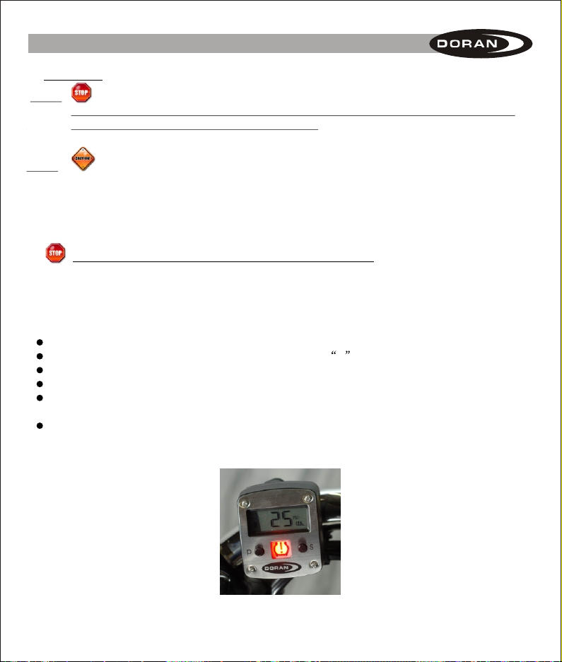
The tire icon on the left side of the screen will indicate the low tire.
The pressure of the low tire will be displayed with the L icon.
A red warning light with a low tire icon will flash once per second (Figure 4-4)
An audible beep will be heard.
If the auxiliary red warning light is also attached to the monitor, it will also flash one time
per second.
This warning will continue until one of the buttons is pressed and at this time the beeper
will be turned OFF, but the warning light(s) will continue to glow until the low-pressure
fault is corrected.
Figure 4-4
8
Inhaltsverzeichnis
Beliebte Mikrofon Handbücher anderer Marken

IK Multimedia
IK Multimedia iRig Stream MIC PRO Bedienungsanleitung

DAPAudio
DAPAudio RM-101 Bedienungsanleitung

AKG
AKG CHM 21 Bedienungsanleitung

Sennheiser
Sennheiser evolution wireless series EM 100 Bedienungsanleitung

Sony
Sony C-48 Bedienungsanleitung

GIGAMEDIA
GIGAMEDIA GGM PAMICUHFG Bedienungsanleitung


