Luxul Xen XAP-1050 Bedienungsanleitung

luxul.com
Simply Connected
Quick Install Guide
XAP-1050
Luxul Xen™ High Performance Outdoor
802.11n Wireless Bridge Client
Use the XAP-1050 to:
Setup a Superior Point-to-Point Bridge Link
Provide up to 40W of Power to any PoE Enabled IP Camera or Device.
Simplify Installation While Minimizing Setup Time and Expense
AP

Quick Install Guide
2© Copyright 2012 Luxul. All rights reserved. Trademarks & Registered Trademarks are property of respective holders.
LUXUL XEN™ HIGH PERFORMANCE OUTDOOR
802.11b/g/n Wireless Access Point
Model Number: XAP-1050
FCC ID: W59XAP1040
IC: 8584A-XAP1040
QUICK INSTALL GUIDE
© 2012 Luxul All rights reserved.
No part of this publication may be modified or adapted in any way, for any
purposes without permission in writing from Luxul. The material in this manual
is subject to change without notice. Luxul reserves the right to make changes to
any product to improve reliability, function, or design. No license is granted, either
expressly or by implication or otherwise under any Luxul intellectual property rights.
An implied license only exists for equipment, circuits and subsystems contained in
this or any Luxul product.
This product is covered by one or more U.S. and foreign patents Patents: 7,379,717,
6,606,075, 6,373,448, other patents pending
DOCUMENT CONVENTIONS
The following graphical alerts are used in this document to indicate notable situations:
NOTE: Tips, hints, or special requirements that you should take note of.
CAUTION: Care is required. Disregarding a caution can result in data
loss or equipment malfunction.
WARNING!: Indicates a condition or procedure that could result in
personal injury or equipment damage.
FCC COMPLIANCE
This device complies with Part 15 of the FCC Rules. Operation is subject to the
following two conditions: (1) this device may not cause harmful interference, and (2)
this device must accept any interference received, including interference that may
cause undesired operation.

a: 14203 Minuteman Drive, Suite 201, Draper, UT 84020-1685 | p: 801-822-5450
Quick Install Guide
3
WARNINGS
XRead all installation instructions and site survey reports, and verify correct equip-
ment installation before connecting the XAP-1050 to its power source.
XRemove jewelry and watches before installing this equipment.
XVerify that the unit is grounded before connecting it to the power source.
XVerify that any device connected to this unit is properly wired and grounded.
XConnect all power cords to a properly wired and grounded electrical circuit.
XVerify that the electrical circuits have appropriate overload protection.
XAttach only approved power cords to the device.
XVerify that the power connector and socket are accessible at all times during the
operation of the equipment.
XDo not work with power circuits in dimly lit spaces.
XDo not install this equipment or work with its power circuits during thunder-
storms or other weather conditions that could cause a power surge.
XVerify there is adequate ventilation around the device, and that ambient tem-
peratures meet equipment operation specifications.
XProducts outside the approved configurations may be in violation of Part 15 of
the FCC Rules.
SITE PREPARATION
XConsult your site survey and network analysis reports to determine specific
equipment placement, power drops, and so on.
XAssign installation responsibility to the appropriate personnel.
XIdentify and document where all installed components are located.
XProvide a sufficient number of power drops for your equipment.
XEnsure adequate, dust-free ventilation to all installed equipment.
XIdentify and prepare Ethernet and console port connections.
XVerify that cable lengths are within the maximum allowable distances for optimal
and certified signal transmission.
GETTING STARTED
System Requirements
XDevices Supporting 802.11b, 802.11g or 802.11n
XWeb Browser (Microsoft IE 8.0 and up, Mozilla Firefox 10 and up, Safari 2.0 and
up, Google Chrome 4.0 and up, Opera 10 and up)
XCAT5 Ethernet Cable

Quick Install Guide
4© Copyright 2012 Luxul. All rights reserved. Trademarks & Registered Trademarks are property of respective holders.
XAC Power Socket (100 – 240 V, 50/60 Hz)
XInternet Connection to View Documentation Online
Package Contents
XXAP-1050 Wireless Access Point
XWeather Resistant RJ45 Connector Gland
X60W AC to DC Power Supply and 25’ Power Cable
XDual Purpose Mounting Bracket for Wall or Pole
XQuick Install Guide
NOTE: If any of the listed items are missing or damaged, please contact
the reseller from whom you purchased for return/replacement.
Safety Information
To maintain the safety of users and property, follow these safety instructions:
XThe XAP-1050 wireless access point is designed for outdoor use and is compliant
with IP-66 standards. However, this does not mean it is waterproof or weather-
proof. Rather, that it is weather and water resistant and care should still be taken
to avoid excessive exposure to heat, moisture, etc.
XDO NOT pull any connected cable with force. When disconnecting cables, do so
by disconnecting first from the access point. When reconnecting, connect the AP
first and then the Power/data source.
XWhen installing the access point, be sure it is firmly secured
XAccessories of this access point, such as mounting screws, the POE injector and
power supply may be dangerous to small children under 3 years of age. KEEP All
ACCESSORIES OUT OF THE REACH OF CHILDREN!
XThe access point may become hot when in use for extended time periods. This is
normal and is not a malfunction. DO NOT install this access point where it will
be exposed to paper, cloth or other flammable materials. If not using the electri-
cal box included with the unit, ALWAYS use a properly shielded and UL listed
electrical box for installation.
XThe XAP-1050 contains no user-serviceable parts. If the access point is not
working properly, contact your dealer and ask for help. DO NOT attempt to
disassemble the access point.
HARDWARE FEATURES AND INSTALLATION
The XAP-1050 high powered access point is designed for optimal performance as
well as for simple and efficient installation and setup. It implements Luxul’s circular
a: 14203 Minuteman Drive, Suite 201, Draper, UT 84020-1685 | p: 801-822-5450
Quick Install Guide
5
polarized directional antenna technology and is packaged for installation outdoors
on a wall or pole. Because the signal generated by the XAP-1050 is directional in
nature, the unit should be placed in a location that allows the antenna face to be
“pointed” towards the desired coverage area.
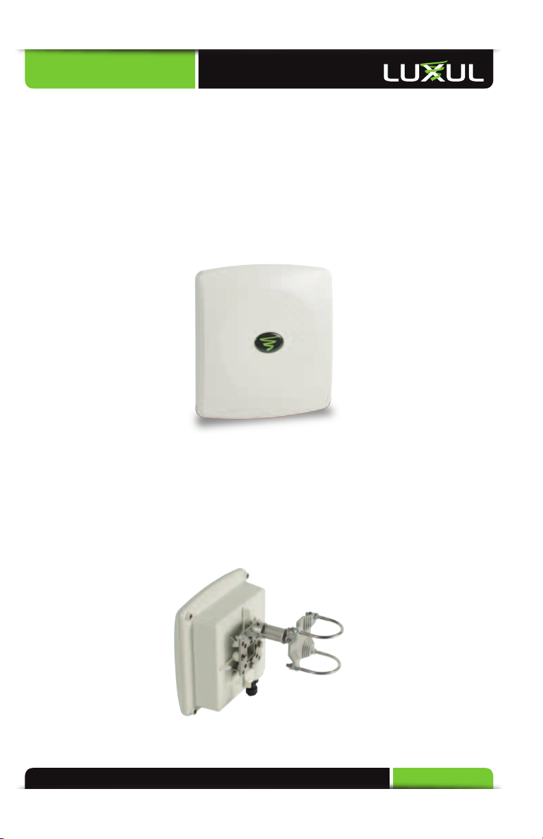
Front View
For maximum weather resistance, the XAP-1050 has no external LED indicators. The
front consists simply of the access point cover with the Luxul icon that indicates
proper top/bottom installation orientation of the access point.
XAP-1050 Front View
Rear View
The rear of the XAP-1050 provides various mounting options. It is designed to
mount optimally to a wall or pole using the included mounting bracket and
hardware.
XAP-1050 Rear View

Quick Install Guide
6© Copyright 2012 Luxul. All rights reserved. Trademarks & Registered Trademarks are property of respective holders.
Bottom View
The bottom of the XAP-1050 provides one RJ-45 connection, and one circular
power connector. The RJ-45 connection is used to deliver both power and data
to the connected PoE enabled device. When installation is complete, a weather
resistant RJ-45 connector gland will cover the RJ-45 connector of the XAP-1050. /
Use the circular power connection to connect the provide 25’ power cable.
XAP-1050 Bottom View
Inside View
For maximum weather resistance, all System LEDs and the Reset button are located
internally. Unless it becomes necessary to do so, opening the XAP-1050 is not
suggested. Note that there are no user serviceable parts. There is also a metal insert
for grounding power.
For troubleshooting, functional validation or system Reset, you will need to open
the XAP-1050. To do so, remove the 4 screws at the back of the unit. After doing so,
carefully lift the base up and to the right as demonstrated below:
View of XAP-1050 Opened

a: 14203 Minuteman Drive, Suite 201, Draper, UT 84020-1685 | p: 801-822-5450
Quick Install Guide
7
CAUTION: Before removing the cover and/or attempting to service
the XAP-1050, be sure to unplug all cables and dismount
the device. Use caution to see that no external elements
are introduced inside the enclosure and that reasonable
precautions are taken to minimize static and electromagnetic
contamination of the electronic components. Avoid touching
any of the internal electronics, except in the case of a Reset.
CAUTION: When lifting the base, be careful not to pull, bend or
otherwise move the base or cover excessively. By simply
lifting the base slightly, you should be able to see the LEDs
as well as access the Reset button. When re-assembling the
unit, be sure to maintain the weather-resistant integrity of
the enclosure by verifying that the rubber seal is properly
seated and the four screws are firmly in place, but not
over-tightened.
With the base lifted to the right, System LEDs and the Reset button can be seen as
shown here:
Reset
Button
Reset Button and LED Location
Status Indicators:
With the unit facing down and the base moved to the right as shown above, the
XAP-1050 has four LEDs, positioned horizontally on the bottom, left side of the
board. When viewed left to right, LEDs are as follows: 1) Bridge Mode (Green); 2)
WLAN Status (Blue); 3) LAN Link/Activity (Amber); and 4) Power (Green).
The following table describes the LED functionality:

Quick Install Guide
8© Copyright 2012 Luxul. All rights reserved. Trademarks & Registered Trademarks are property of respective holders.
Indicator Name Description
Bridge Mode On Bridge is connected
Flashing Bridge Mode enabled but not connected
Off The AP is in default “Access Point” mode.
WLAN Status On The wireless radio is active and wireless
access is enabled
Off The wireless radio is not active and wireless
access is disabled
LAN Link/Activity On There is an active Ethernet connection
Flashing Indicates Ethernet activity
Off There is no active Ethernet connection
Power On The power is on
Off No power, check power connections
At startup, the Green Power LED will stay on while the amber LAN Link light
flashes. The blue LED will come on once the XAP-1050 wireless radio is active.
Reset Button:
The Reset button is used to clear the current settings of the XAP-1050 and restore
factory default settings.
To Restore the Default Settings: With the XAP-1050 powered on, press and hold the
Reset button for 15 seconds. When the Power LED comes on again, release the reset
button. The XAP-1050 will be set to factory defaults.
CAUTION: Pressing and holding the Reset button will remove any
custom configurations done to the XAP-1050.
Environmental Requirements
XEthernet cable to provide Power and Data to the XAP-1050.
XA computer supporting TCP/IP and equipped with a Web browser. Supported
Web browser versions include Microsoft IE 7.0 and up, Safari 1.0 and up, Mozilla
Firefox 1.0 and up, and Google Chrome 5.0 and up. The Web browser is used to
configure the XAP-1050.
XThe XAP-1050 uses 36-57VDC power. The power supply requires AC 100V ~ 240V,
50Hz ~ 60Hz.

a: 14203 Minuteman Drive, Suite 201, Draper, UT 84020-1685 | p: 801-822-5450
Quick Install Guide
9
XTemperature of the operating environment: -4F~131F (-20C to 55C). Be sure to
place the access point away from heat generating devices.
XHumidity of the operating environment: 5%-95% non-condensing. Do not place
the access point in an extremely dirty or damp location.
XKeep the access point away from strong electromagnetic fields (i.e. Air
Conditioner compressors, fluorescent light ballasts, CRT monitors/televisions,
etc.), and free from vibration, dust and direct sun light.
Hardware Installation
Access Point Placement
This XAP-1050 implements Luxul’s Circular Polarized directional antenna technol-
ogy. For maximum efficiency, it should be aimed towards the area to which you
would like to provide coverage. With this in mind, the ideal placement option is
usually on an outside wall or pole pointed into the coverage area.
XAP-1050 Suggested Mounting Location
Mounting the Access Point on a Wall or Pole
The XAP-1050 can be mounted directly to a wall or pole using the included mount-
ing bracket.
The XAP-1050 mount assembles as show above. The u-bolts may be removed and
the plate may be mounted directly to a wall using your hardware.

Quick Install Guide
10 © Copyright 2012 Luxul. All rights reserved. Trademarks & Registered Trademarks are property of respective holders.
CAUTION: Do not drill holes in the enclosure or the weather proofing
will be compromised and your warranty voided.
Assembling the Weather Resistant RJ-45 Connector Gland
To ensure proper protection from the elements, the weather resistant RJ-45 con-
nector gland must be installed correctly. To do so requires the installer to termi-
nate the Ethernet Cable that will be plugged into the XAP-1050. The diagram below
indicates the correct assembly for the RJ-45 Connector Gland.
RJ-45 Connector Weather Resistant Gland assembly
NOTE: Category-5, super Category-5 or Category-6 unshielded twisted
pair (CAT5/CAT5e/CAT6 UTP) cables can be used. For best
results, it is recommended that Category-6 shielded twisted pair
be used to ensure stable data transmission at highest data rates.
Once the RJ45 Connector Gland has been assembled and the Ethernet Cable has
been terminated, the cable can now be plugged into the XAP-1050. You can now at-
tach the RJ-45 Connector Gland by placing it over the cable connector and turning
it clockwise until it is firmly secured. At this time, also tighten the gland around the
cable by turning it clockwise and thus creating a water-tight seal.
Connecting to the Power Source
The included power supply needs to be hard wired into a suitable VAC source
according to local electrical wiring codes. ACL (Brown wire, VAC Live) needs to be
connected to the hot (typically black for 110VAC in the US) and the ACN (Blue wire,
VAC Neutral) needs to be connected to the neutral (typically white for 110VAC in
the US) AC feed.
The output of the power supply is 48VDC with V+ (Red) and V- (Black, ‘Ground’).
Connect these to the supplied XAP-1050 pigtail. Connect Red to Red and Black to
Black.
Inhaltsverzeichnis
Andere Luxul Netzwerk-Hardware Handbücher


Beliebte Netzwerk-Hardware Handbücher anderer Marken

Matrix Switch Corporation
Matrix Switch Corporation MSC-HD161DEL Bedienungsanleitung

B&B Electronics
B&B Electronics ZXT9-IO-222R2 Bedienungsanleitung

Yudor
Yudor YDS-16 Bedienungsanleitung

D-Link
D-Link ShareCenter DNS-320L Bedienungsanleitung

Samsung
Samsung ES1642dc Gebrauchsanweisung

Honeywell Home
Honeywell Home LTEM-PV Montageanleitung


