
LXI LX7007 pro IGC Bedienungsanleitung
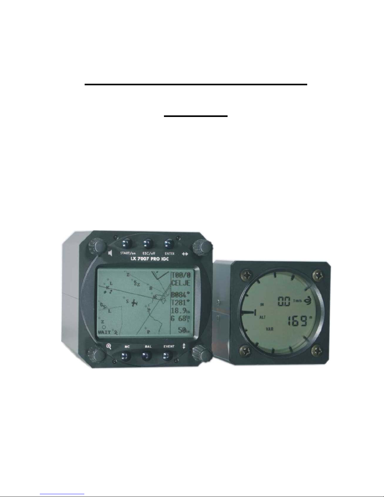
LX7007 pro IGC
V1.0
Variometer and GPS-Navigation System
Draft

LX 7007 pro IGC V1.0 Apr.2005
Page 2
Contents
1 GENERAL...........................................................................................................................................................................4
1.1 TECHNICAL DATA...........................................................................................................................................................4
1.2 ROTARY SWITCHES AND KEYS (BUTTONS) ......................................................................................................................5
1.2.1 ON/START button - Switching the Instrument ON and OFF ..............................................................................5
1.2.2 MODE selector (rotary switch).............................................................................................................................6
1.2.3 UP/DOWN selector (rotary switch)......................................................................................................................6
1.2.4 ENTER button.......................................................................................................................................................6
1.2.5 ESC/OFF button ...................................................................................................................................................6
1.2.6 EVENT button.......................................................................................................................................................6
1.2.7 MC and BAL buttons.............................................................................................................................................6
1.2.8 ZOOM (rotary switch) ..........................................................................................................................................6
2 OPERATING MODES...........................................................................................................................................................7
2.1 SETUP ..........................................................................................................................................................................7
2.1.1 SETUP of Options not Requiring the Password ...................................................................................................7
2.1.1.1 QNH RES (QNH and Safety Altitude) ................................................................................................................................ 8
2.1.1.2 LOGGER (FLIGHT RECORDER)..................................................................................................................................... 8
2.1.1.3 INIT................................................................................................................................................................................... 11
2.1.1.4 DISPLAY.......................................................................................................................................................................... 12
2.1.1.5 TRANSFER ...................................................................................................................................................................... 12
2.1.1.6 PASSWORD ..................................................................................................................................................................... 12
2.1.2 SETUP of Options Requiring Access by Password,...........................................................................................13
2.1.2.1 AS SELECT (selection of airspace section) ...................................................................................................................... 13
2.1.2.2 TP (Turn point)................................................................................................................................................................ 13
2.1.2.3 OBS. ZONE (Observation Zone) ...................................................................................................................................... 14
2.1.2.4 WARNINGS - Airspace Penetration and Height Warnings ........................................................................................... 19
2.1.2.5 SETUP GPS ...................................................................................................................................................................... 20
2.1.2.6 UNITS............................................................................................................................................................................... 20
2.1.2.7 GRAPHIC ......................................................................................................................................................................... 21
2.1.2.8 EDIT PILOTS (Pilot list) ................................................................................................................................................. 23
2.1.2.9 SETUP NMEA.................................................................................................................................................................. 25
2.1.2.10 SETUP PC......................................................................................................................................................................... 25
2.1.2.11 DEL TP/TSK..................................................................................................................................................................... 25
2.1.2.12 GLIDER POLAR .............................................................................................................................................................. 25
2.1.2.13 LOAD................................................................................................................................................................................ 26
2.1.2.14 SETUP TE COMP. ........................................................................................................................................................... 26
2.1.2.15 SETUP INPUT.................................................................................................................................................................. 27
2.1.2.16 SETUP LCD INDICATOR (LCD – Vario Indicator) ...................................................................................................... 27
2.1.2.17 COMPASS ........................................................................................................................................................................ 29
2.1.2.18 ENL (Engine Noise Level)............................................................................................................................................... 29
2.1.2.19 PAGE 1 (Main Navigation Page) ...................................................................................................................................... 29
2.1.2.20 PAGE 3 (Additional Navigation Page)............................................................................................................................. 30
2.1.2.21 SETUP AUDIO................................................................................................................................................................. 30
2.1.2.22 SETUP ALARMS ............................................................................................................................................................. 30
2.2 NAVIGATION FUNCTIONS .............................................................................................................................................30
2.2.1 GPS Page............................................................................................................................................................30
2.2.2 NEAR AIRPORT .................................................................................................................................................31
2.2.3 APT Airports, TP Turn Points and TSK Tasks....................................................................................................31
2.2.3.1 Navigation in APT, TP or TSK ......................................................................................................................................... 32
2.2.3.2 Airport Selection, Team and Wind Calculation................................................................................................................. 33
2.2.4 TP - Turn Points .................................................................................................................................................35
2.2.4.1 TP SELECT ...................................................................................................................................................................... 35
2.2.4.2 TP EDIT............................................................................................................................................................................ 36
2.2.4.3 TP NEW............................................................................................................................................................................ 36
2.2.4.4 TP delete ........................................................................................................................................................................... 36
2.2.4.5 TEAM ............................................................................................................................................................................... 36
2.2.4.6 WIND................................................................................................................................................................................ 36
2.2.4.7 TP QUICK - Storing of actual position ............................................................................................................................ 36
2.2.5 TSK - Task..........................................................................................................................................................37
2.2.5.1 TSK - SELECT ................................................................................................................................................................ 38
2.2.5.2 TSK - EDIT..................................................................................................................................................................... 38
2.2.5.3 TSK - NEW..................................................................................................................................................................... 40
2.2.5.4 TSK - DECLARE............................................................................................................................................................ 40
2.2.6 STATISTICS........................................................................................................................................................41

LX 7007 pro IGC V1.0 Apr.2005
Page 3
2.2.6.1 Statistics during flight ....................................................................................................................................................... 41
2.2.6.2 Statistics after flight........................................................................................................................................................... 42
2.3 VARIOMETER AND ALTIMETER.....................................................................................................................................43
2.3.1 Smart Vario description......................................................................................................................................44
2.3.2 Altimeter .............................................................................................................................................................44
2.3.2.1 IGC barogram recalibration procedure .............................................................................................................................. 44
2.3.3 Speed command ..................................................................................................................................................44
2.3.4 Final glide calculation........................................................................................................................................45
2.4 FLYING WITH THE LX 7007 PRO IGC..........................................................................................................................45
2.4.1 Switching ON and selecting pilot........................................................................................................................45
2.4.2 SET Elevation (take off elevation input) ............................................................................................................46
2.4.3 Preflight check ....................................................................................................................................................47
2.4.4 Performing the flight...........................................................................................................................................47
2.4.4.1 Preparing a task ................................................................................................................................................................. 47
2.4.4.2 Starting a task.................................................................................................................................................................... 48
2.4.4.3 Automatic swap on reaching a TP using standard task and AAT ...................................................................................... 49
2.4.4.4 Use of MOVE function ..................................................................................................................................................... 49
2.4.4.5 TSK END.......................................................................................................................................................................... 50
2.4.4.6 Procedure after landing ..................................................................................................................................................... 50
2.4.4.7 SIMPLE TASK ................................................................................................................................................................. 51
3 PC, PDA AND COLIBRI/LX20 COMMUNICATION ..........................................................................................................51
3.1 COMMUNICATION WITH PC ..........................................................................................................................................52
3.1.1 Some help having problems with communication ...............................................................................................53
3.1.1.1 General .............................................................................................................................................................................. 53
3.1.1.2 Troubleshooting with LXE................................................................................................................................................ 54
3.1.1.3 Recommended LXE settings for safe communication....................................................................................................... 55
3.1.2 Having problems downloading flights (read selected flight-command)..............................................................56
3.1.3 Additional help from LX navigation....................................................................................................................56
3.2 COMMUNICATION WITH PDA .......................................................................................................................................57
3.2.1 Connect procedure to PDA.................................................................................................................................57
3.3 COMMUNICATION BETWEEN LX 7007, COLIBRI OR LX 20 ...........................................................................................58
3.3.1 Data transfer LX 7007-LX 20 .............................................................................................................................58
3.3.2 Data transfer LX 7007-Colibri ...........................................................................................................................58
4 INSTALLATION ................................................................................................................................................................59
4.1 INSTALLATION OF PDA UNITS......................................................................................................................................60
4.2 LX 7007 PRO IGC FULL CONFIGURATION (ALL CONNECTIONS PLUG AND PLAY) ...........................................................61
4.3 WIRING ........................................................................................................................................................................63
4.4 TREE STRUCTURE DIAGRAM.........................................................................................................................................65
5 PASSWORDS.....................................................................................................................................................................66
6 OPTIONS ..........................................................................................................................................................................67
6.1 LX 7007 PRO IGC - COMPASS MODULE .....................................................................................................................67
6.1.1 General ...............................................................................................................................................................67
6.1.2 Installation of the compass module.....................................................................................................................68
6.1.2.1 Where to install: ................................................................................................................................................................ 68
6.1.2.2 First test after installation: ................................................................................................................................................. 68
6.1.3 Adjusting the compass module:...........................................................................................................................68
6.1.4 Final test:............................................................................................................................................................68
6.1.5 Wind calculation during flight ............................................................................................................................69
6.2 LX 7007 PRO IGC – REMOTE CONTROL UNITS ............................................................................................................70
6.2.1 Remote control keyboard type.............................................................................................................................70
6.2.1.1 General .............................................................................................................................................................................. 70
6.2.1.2 Getting started ................................................................................................................................................................... 70
6.2.1.3 Electronic connection........................................................................................................................................................ 71
6.2.2 LX 7007 PRO IGC – Remote K- Stick mounted unit...........................................................................................71
6.2.2.1 General .............................................................................................................................................................................. 71
6.2.2.2 LX 7007 PRO IGC Remote K configuration..................................................................................................................... 71
6.2.2.3 Stick handle with keys....................................................................................................................................................... 71
7 REVISION HISTORY .........................................................................................................................................................72

LX 7007 pro IGC V1.0 Apr.2005
Page 4
1 General
The instrument consists of two units, the LX 7007 DU main unit, and the LX 7007 AU LCD Vario indicator unit. The
80mm diameter (3") main unit LX 7007 DU is fitted with an integral 12 channel GPS receiver and a high resolution
display with 160x240 pixels. The 57 mm diameter (2 1/4") LX 7007 AU is a new design with its own integral micro
processor and communicates with the LX 7007 DU via the RS 485 system bus. Optionally, additional LX digital Vario
indicators can be daisy chained using the RS 485 bus.
Vario functions include:
• Vario, Netto, Relative (Super Netto) and Averager (new algorithms for vario signal acquisition added)
• Speed command
• Final glide calculator
• TE compensation is selectable for either pneumatic TE tube, or electronic TE
Navigation functions include:
• Airport and airspace database for Europe or USA (up to 5000 airports)
• 600 turn points
• 100 tasks
• Statistics
• Display of nearest airports
• Support of AAT (assigned area task)
What does LX 7007 PRO IGC mean?
The LX 7007 PRO IGC has an integral IGC approved flight recorder utilizing a dedicated pressure sensor for pressure
altitude recording based on 1013.2 hpA (29.92"). An integral engine noise capability is fitted for self sustaining and self
launching sailplanes. The firmware ensures data integrity and meets all IGC requirements regarding security of the
flight record data.
1.1 Technical data
• Power 8-16 V DC
• Consumption 400mA @ 12V (without audio)
• 80mm (3") standard Aircraft cut-out for LX 7007 DU
• 57mm (2 1/4") standard Aircraft cut-out for LX 7007 AU
• Length 120 mm (incl. connector)
• There physically separated com. Ports:
-PDA port with 5V power supply, delivers NMEA or allows data exchange LX 7007-PDA
- PC port
- IGC com port with IGC standard connector, suitable to connect Colibri or LX 20
-User com. port for some future applications
• Drives SeeYou mobile, Navigator, Winpilot….
• PDA communication with Connect LX
• 12 Channel GPS receiver
• memory space to store the whole European airspace
• External speaker
• Built in fuse to prevent damages in stead of a short on 485 bus
• Data compatible with LX 20 and Colibri
• IGC approved flight recorder
• Wiring
• Additional LCD Vario, rear seat unit, remote control and compass options can be connected via the RS 485 bus
• Weight: 800g

LX 7007 pro IGC V1.0 Apr.2005
Page 5
1.2 Rotary switches and keys (buttons)
The following controls are mounted on the front face of the LX7007 DU
• Four rotary selector switches
• Six push buttons
The LX7007AU is an indicator only and has no controls; the displayed information being controlled from the
LX7000DU
1.2.1 ON/START button - Switching the Instrument ON and OFF
The ON/START button is multifunctional. If the instrument is not already powered up, a short press on the
ON/START button will switch the instrument ON. To switch the instrument OFF, press the ESC/OFF button for a
few seconds and the instrument will switch off. If an attempt is made to switch the instrument off during flight, the
instrument requires confirmation from the pilot, so the LX 7007 PRO IGC cannot be switched off by mistake. On
powering the unit, the first screen shows the firmware version, database version, serial number of the unit, and total
memory in hours available for IGC flight records. After a few seconds, a second screen shows details of the glider and
pilot. The unit is equipped with a facility of storing up to 30 pilot names. If no names are stored, the unit shows the
pilot name as UNKNOWN. By rotating the UP/DOWN selector, the display scrolls through the programmed pilots.
Once the correct pilot is selected, pressing the ENTER button selects the airfield elevation screen and the current
elevation should be entered, again using the UP/DOWN selector and the ENTER button. Similarly, the current QNH
should also be entered. The airfield elevation input is mandatory while the QNH input optional (See Para 3.1.1.1)
During flight the same button is used to start the task, to see more characters of airport names and, in the edit
menu, to go back one step if an error has been made (see paragraph APT).
ZOOM selector
VOLUME selector
START/ON button ESC/OFF button ENTER button
MODE selector
MC button BALLAST button EVENT button
UP/DOWN selector
Note!:
During flight, if main power is lost for a few seconds, the flight recorder will not produce two flights. The most
important flight parameter, altitude will remain, which means that the final glide is not interupted.
LX 7007 pro IGC V1.0 Apr.2005
Page 6
1.2.2 MODE selector (rotary switch)
The mode selector is used to change modes of operation. This switch has the highest priority in the system. Whenever
it is operated, a mode change will occur.
1.2.3 UP/DOWN selector (rotary switch)
This rotary switch has a lower priority than the mode selector switch and is active all the time in the selected mode. It is
mainly used for selecting sub menus during navigation and to scroll in the edit menu.
1.2.4 ENTER button
The main function of this key is confirmation, and to start edit procedures.
1.2.5 ESC/OFF button
This is a multifunctional key, which has two main functions. If it is pressed and held for a few seconds, then the
instrument will turn OFF as outlined in para 2.2.1 above.
If a short press is made, then the button has the following functions:
• The display will jump to the menu of the next higher level (in edit only)
• During alpha-numeric input with the cursor active (blinking), ESC confirms the whole line (It is not necessary to
press ENTER few times)
• Some special functions can be activated using ESC as described in subsequent paragraphs
1.2.6 EVENT button
Activates the Event function (see Chapter 3.1.1.2, Flight Recorder)
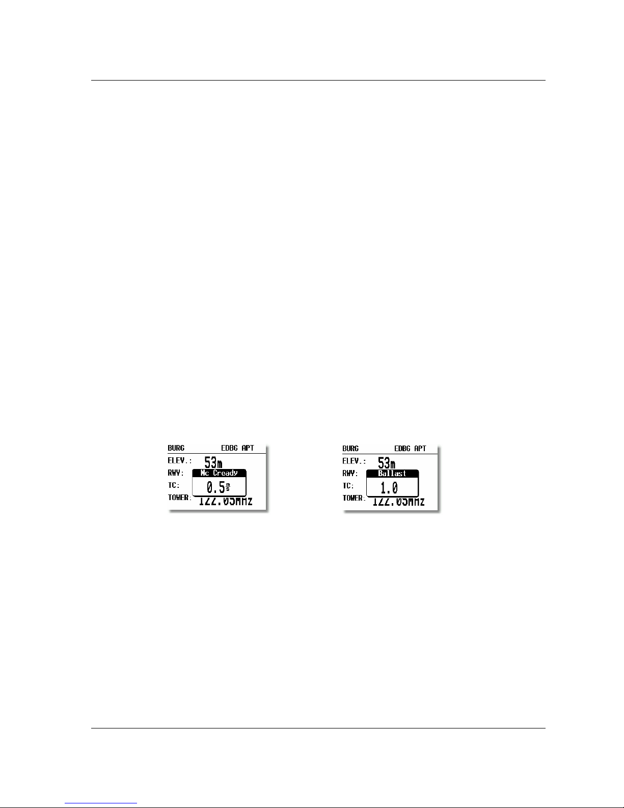
1.2.7 MC and BAL buttons
Pressing these buttons activates the Mc Cready (MC) and ballast setting as shown below. The value is then changed with
the UP/DOWN-selector. There is no secondary function of these buttons.
1.2.8 ZOOM (rotary switch)
This is a multifunctional rotary switch. While its main function is to change the zoom level in the graphic mode, it can
also be used as follows:
• To select turn points when in the main TP page
• To select task when in the main TSK page
• If an error is made during editing, it is possible to move the cursor back by rotating this knob. This can only be
done if 'editing' is active which is shown by the cursor blinking
LX 7007 pro IGC V1.0 Apr.2005
Page 7
2 Operating modes
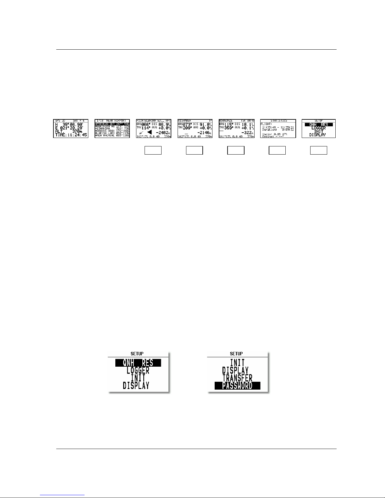
The LX 7007 PRO IGC has 7 modes or main menus. All of them are selectable directly by rotating the MODE switch.
The diagram shows the menu (mode) structure of LX 7007 PRO IGC.
Navigation menus (APT, TP and TSK) have sub menus, which can be selected using the Up/Down switch.
GPS GPS status, no inputs possible
NEAR Near airport, select one airport of interest, no further inputs are possible
APT Navigation and selection of airports
TP Navigation, selection and editing of turn points
TSK Navigation, selection and editing of tasks
STAT Flight statistics and logbook
SETUP has two levels. The first level, for which no password is required, is fully accessible. To activate the second
level, it is necessary to input a password. The password is not top secret; it is the same for all instruments and is freely
available.
96990
The selection of the system parameters that are fixed, such as glider type, units, polar etc, are only access able by
entering the password. This facility prevents that well known gliding club pest, "the random knob twiddler" from
changing the important fixed parameters just before you launch on the flight of the year! Once you are airborne, then
the password is not necessary - the second level can be entered simply by selecting PASSWORD and pressing
ENTER.
2.1 SETUP
2.1.1 SETUP of Options not Requiring the Password
The first five options are selected with the UP/DOWN switch and can be entered at any time; they contain no system
settings.
Once the desired option has been selected, press ENTER to access the sub-menu.
⇓ ⇓ ⇓ ⇓ ⇓
⇓ ⇓ ⇓ ⇓ ⇓
GPS NEAR APT TP TSK STAT SETUP
⇐
MODE⇒

LX 7007 pro IGC V1.0 Apr.2005
Page 8
2.1.1.1 QNH RES (QNH and Safety Altitude)
Input Procedure:
• Use the UP/DOWN selector to choose the item it is required to change (QNH, MG.VAR, ALT.R. or BUGS)
• Press ENTER
• Use UP/DOWN to select the value required and press ENTER to input it
• Once all changes are complete, press ESC top return to SETUP menu
QNH: Using this feature it is possible to offset the altitude datum, which could have changed due to pressure changes
during the flight. During the initial power up sequence, an option to enter the QNH was presented. If the actual QNH
was entered at that stage, then this feature is active. If the QNH feature was 'stepped over' during power up, then this
function is not active. As changing the QNH influences the indicated altitude, care should be taken when changing the
value as an incorrect setting can upset the final glide calculation.
MG. V. If the GPS receiver calculates magnetic variation then AUTO will be displayed here and no input is possible.
If AUTO is not displayed, then the GPS receiver is not calculating magnetic variation and it is obligatory to input the
magnetic variation for the area being flown over. If this is not done, then all calculated winds and tracks flown will be
true and not magnetic.
ALT.R. This setting is the altitude reserve or safety altitude, and is the height that the instrument adds to the final glide
altitude required so that the glider arrives over the final glide destination at the selected safety altitude. After safety
altitude input, the pilot has has to keep final glide indicator on 0 to arrive on safety altitude.
BUGS: This sets the polar degradation because of “buggy” wings. The input is in percentage degradation of glide
ratio. (5%, means glide ratio degradation is 5%)
2.1.1.2 LOGGER (FLIGHT RECORDER)
The flight recorder is fully approved by the IGC (A sub-committee of the FAI.) and will produce secure flight records
that are acceptable for all FAI requirements including world records.
After selecting LOGGER and pressing ENTER, the following flight recorder settings are accessible.
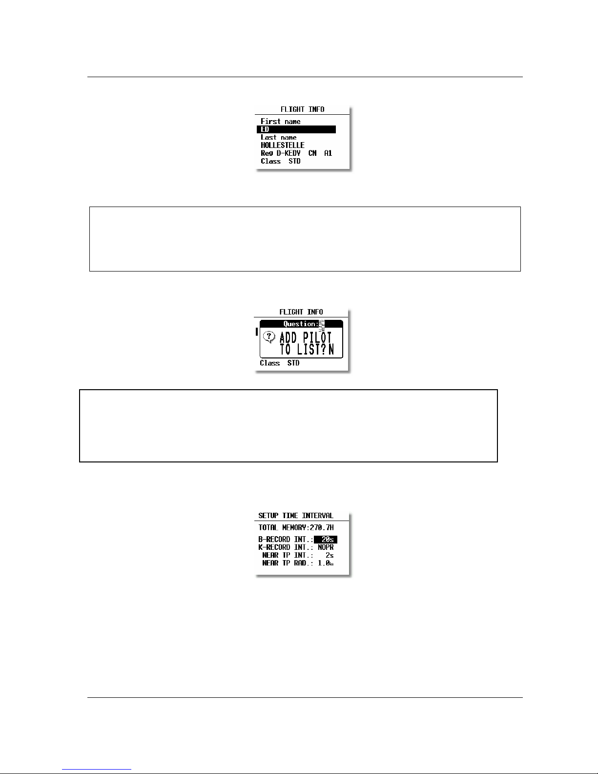
FLIGHT INFO All important data, such as the pilot's name, glider type, glider registration, competition number and
competition class can be entered. The data is entered with the ENTER, UP/DOWN and ESC routine. This data is
subsequently written into the 'H' record of the IGC flight log. Alternatively, this data can be entered with a PC and the
LXe-program; or via a Colibri or LX20 (see Chapter 4).
LX 7007 pro IGC V1.0 Apr.2005
Page 9
Before leaving the FLIGHT INFO menu, the actual name can be saved into pilot list, if not already present.
LOGTIME is an important parameter as it shows the total memory available for recording the flight.
TOTAL MEMORY is the capacity of memory in hours that can be stored and only depends on the settings. It does
not decrease as flights are stored and will only change after new settings have been made in the setup. If the memory is
full, the oldest flights will be overwritten without warning. The total memory simply indicates how many hours of
flight can be made without loosing any flight data before overwriting occurs.
B-RECORD: This is the main IGC record in which position, GPS altitude, pressure altitude, UTC and GPS status are
stored. The default interval is 12 seconds and it can be changed. As the interval is reduced, the Total Memory will be
seen to decrease.
Note!:
The instrument is cabable of storing up to 30 different pilot's names. Each pilot's name, which can be password
protected, can have different flight information programmed into it. This is useful if one likes to fly with a custom
polar, fly the glider in different configurations, or fly in decentralized competitions, Online-Contest, Barron-Hilton-
Cup, etc. For more information on configuring pilot names see 3.4.1, and for for setting custom polars see 3.1.2.10.
Note!:
If only one pilot flies the glider, then after entering his name, it is not necessary to enter it into the list. In the
above screen 'N' should be selected to do this. The name will then appear automatically on instrument power up
together with all the parameters that have been set. An exception to this is if he flies the glider in two different
configurations; then he should list his name twice, e.g once with a suffix of 15m and again with a suffix of 18m
with different polars in each name.

LX 7007 pro IGC V1.0 Apr.2005
Page 10
K-RECORD: This record can be used to store non-essential flight parameters and is not active by default. It should not
be activated unless the IGC record format is fully understood. If required to be activated, the J-Record (see below) will
select the flight parameters that are stored in the K-Record.
NEAR TP INT: This setting enables the fixing rate set by the B-Record to be increased close to a turnpoint to ensure
that a fix is obtained in the observation zone.
NEAR TP RAD: This setting defines the radius from the turnpoint at which increased fixing rate is to start.
(I) RECORD: This record permits additional flight parameters to be added to the B-Record. Except for ENL (Engine
Noise Level), they are all de-activated by default. They can be activated if required by toggling the 'N' to 'Y'.
-FXA: current horizontal accuracy of GPS
-VXA: current vertical accuracy of GPS
-RPM: engine RPM
-GSP: ground speed
-IAS: indicated airspeed
-TAS: TAS
-HDM: mg. heading
-TRM: magnetic track
-TRT: true track
-TEN: total energy
-WDI: wind direction
-WVE. wind
-VAR: vario
-ENL: engine noise level (default Y)
Each setting activated will reduce the total memory capacity.
(J) RECORD: The J-Record defines the flight parameters that are to be stored in the K-Record. These parameters are
the same as those used for the I-Record. Using this record will reduce the total memory by about half.
EVENT This option programs what happens on pressing the EVENT button. On pressing the button, the flight
recorder places a special marker, called a PEV (Pilot Event), in the IGC flight record At the same time, it causes the
recorder to run at a different fix interval for a certain time. The interval and time are set up in this option.
Competition rules may require the EVENT to be activated at some stage during the flight.
Example:
The setting above will cause the recorder to log 30 additional fixes at 2-second intervals on pressing the EVENT button.
Note!:
Unless the user has a good understanding of the composition and use of IGC flight records, then it is recommended
that, other than the ENL, no alterations are made to the default selections.
Inhaltsverzeichnis


