MacroAir Technologies Controller 4 Bedienungsanleitung

© 2017 MacroAir Technologies Toll Free: 866 668 3247 Fax: 909 890 2313 www.macroairfans.com 1
Rev. Date 032217

© 2017 MacroAir Technologies Toll Free: 866 668 3247 Fax: 909 890 2313 www.macroairfans.com 1
Rev. Date 032217
Table of Contents
Caution & Safety ................................................................................................................................. 2
Fan Network Ordering ........................................................................................................................ 3
Network Installation
Network Wiring Requirements .................................................................................................. 4
Network Wiring Configurations ................................................................................................. 5
Temp/Humidity Sensor Location (Optional) ............................................................................... 6
Network Excess Cable ................................................................................................................ 7
Wiring Diagrams ......................................................................................................................... 8
Connection Method ..................................................................................................................... 9
Temp/Humidity Sensor Installation (Optional) .......................................................................... 12
Connect Fans To Network .......................................................................................................... 13
Configuration and Operation
Screen Setup ............................................................................................................................... 14
Screen Flow ................................................................................................................................ 15
Controller Home Screen ............................................................................................................. 16
Setpoint ....................................................................................................................................... 17
Fan Select Screen ....................................................................................................................... 18
Fan Settings Screen.................................................................................................................... 19
Address Screen ........................................................................................................................... 2 0
Mkey ............................................................................................................................................ 2 1
Fan Diameter Screen .................................................................................................................. 22
Startup Sequence ....................................................................................................................... 23
Controller Dimensions ....................................................................................................................... 24
Warranty Information ......................................................................................................................... 25
Technical Support ............................................................................................................................... 26

© 2017 MacroAir Technologies Toll Free: 866 668 3247 Fax: 909 890 2313 www.macroairfans.com 2
Rev. Date 032217
Caution & Safety
READ THE ENTIRE MANUAL BEFORE OPERATING THE FAN. Ensure that all safety practices
and instructions are followed during the installation, operation, and servicing of the fan. Failure
to apply these safety practices could result in death or serious injury. If you do not understand
the instructions please call our Technical Department for guidance (Technical Support contact
information can be found on page 26.
All fan controls and incoming power should only be installed by qualified technicians familiar
with the requirements of the NEC and local codes. Refer to appropriate portions of this manual
for other important requirements. Failure to follow these guidelines will void the manufacturer’s
warranty.
Installation is to be in accordance with the national electrical code, ANSI/NFPA 70-1999 and local
codes.
HAZARD OF ELECTRIC SHOCK, EXPLOSION, OR ARC FLASH.
Read and understand this manual before installing or operating a fan unit. Installation,
adjustment, repair, or maintenance must be performed by qualified personnel.
The user is responsible for compliance with all international and national electrical code
requirements with respect to grounding of all equipment.
Many of the parts of this unit operate at line voltage. DO NOT TOUCH.
Install all covers before applying power or starting and stopping the unit.
DAMAGED EQUIPMENT
Do not operate or install any fans or fan accessories that appear to be damaged.
Failure to follow this instruction can result in death, serious injury, or equipment damage.
MAINTENANCE AND SERVICE:
If the fan does not operate properly using the procedures in this manual, BE CERTAIN TO
REMOVE ALL POWER TO THE UNIT and contact our technical department for further assistance.
Keep all body parts clear of moving part at all times.
All electrical troubleshooting and repair must be done by a qualified technician and meet all
applicable codes.
REFER TO FAN INSTALLATION MANUAL(S) FOR FURTHER MAINTENANCE INFORMATION.

© 2017 MacroAir Technologies Toll Free: 866 668 3247 Fax: 909 890 2313 www.macroairfans.com 3
Rev. Date 032217
Fan Network Ordering
It is important to purchase fans that are setup for a network. MacroAir customizes fans to
operate in a network by:
1) Addressing the fans and
2) Supplying an additional 15ft piece of CAT5
Note: If you did not order your fans for a network by default they will all have Node Address “2”,
and you will be missing necessary materials. Contact technical support to modify your fans for
networking.

© 2017 MacroAir Technologies Toll Free: 866 668 3247 Fax: 909 890 2313 www.macroairfans.com 4
Rev. Date 032217
Network Wiring Requirements
Network Wiring Requirements:
• Use of Twisted Pair, CAT5e (or higher grade) shielded cable
• Minimum 24 AWG (0.5mm) cross section
• Ground the shielding and drain wire at only one point of the cable run
• Route wires as far away as possible from high voltage AC cables, fluorescent lights, arc
welders, and other equipment that transmits EMI (electromagnetic interference).
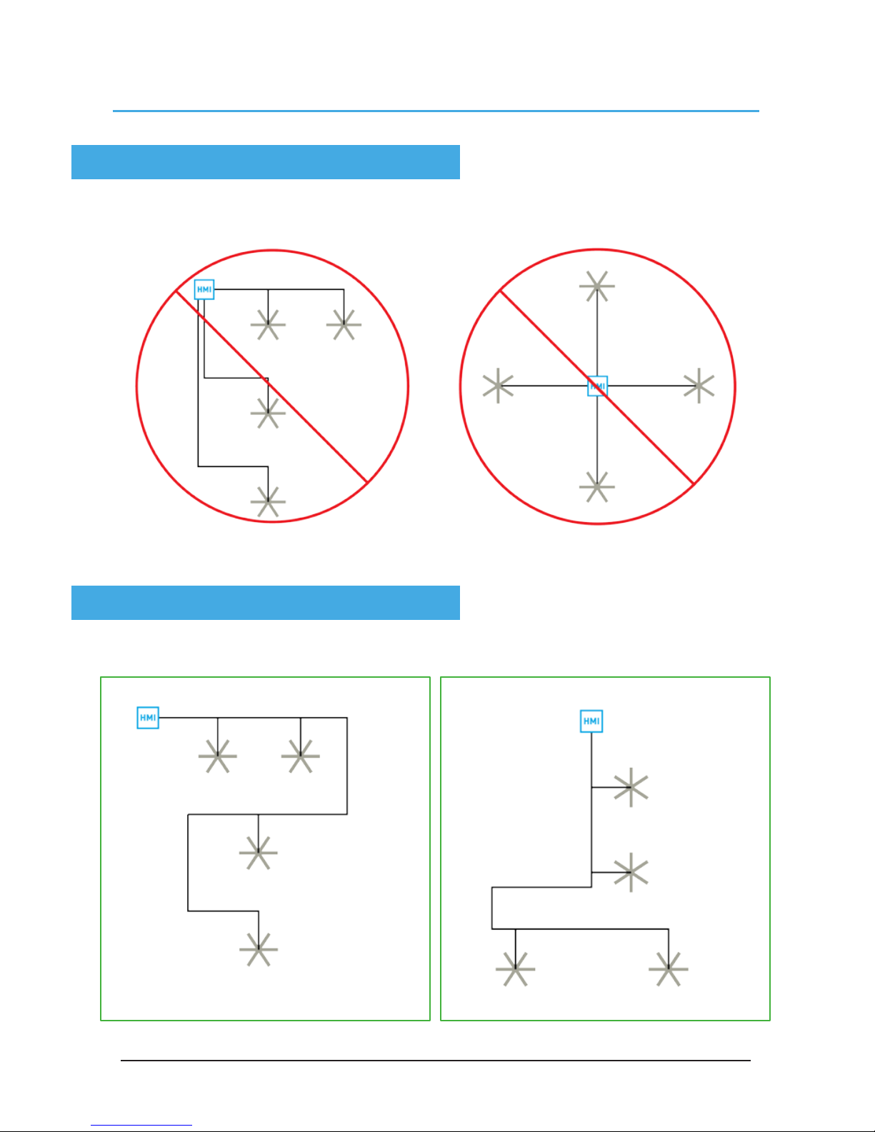
Networked MacroAir fans must be connected in one single line, referred to in this document as
a “daisy chain”. The characteristics of a proper daisy chain are: one beginning (Controller 4) and
one end (last fan).
If the fans are not connected in one line/chain there will be a de-gradation of the communication
signal and the network may not function as intended (fans in the network may not operate).
Daisy Chain
© 2017 MacroAir Technologies Toll Free: 866 668 3247 Fax: 909 890 2313 www.macroairfans.com 5
Rev. Date 032217
Improper Wiring Configuration
One Beginning, One End
Proper Wiring Configuration
Network Wiring Configurations

© 2017 MacroAir Technologies Toll Free: 866 668 3247 Fax: 909 890 2313 www.macroairfans.com 6
Rev. Date 032217
Temp/Humidity Sensor Location
(Optional)
The optional sensor can be placed between two fans or between the controller and a fan as per
the diagrams below. Refer to page 12 for more information.

© 2017 MacroAir Technologies Toll Free: 866 668 3247 Fax: 909 890 2313 www.macroairfans.com 7
Rev. Date 032217
Excess Cable at Connection Point
Trim Excess Cable
Network Excess Cable
With noise being emitted throughout a typical industrial/commercial environment, extra cable
should not be coiled up as the coil itself will create noise/interference in the communication
signal. There should be no more than two feet of excess cable at each connection point.
If more than two feet of cable is needed for future relocation of the fan, run the cable up toward the
ceiling and back down in a horseshoe shape.
ALWAYS AVOID SHARP BENDS OF THE CABLE.

© 2017 MacroAir Technologies Toll Free: 866 668 3247 Fax: 909 890 2313 www.macroairfans.com 8
Rev. Date 032217
Wiring Diagrams
Typical T-Splice of CAT5
Wiring: CAT5 Pin-Out

© 2017 MacroAir Technologies Toll Free: 866 668 3247 Fax: 909 890 2313 www.macroairfans.com 9
Rev. Date 032217
Connection Method
1. Take the incoming CAT5 from the network, the CAT5 from the fan, and the CAT5 going to the
rest of the network. Give some slack (no more than 24”) on each CAT5 to strip the wires and
splice them together. Run the slack up towards the ceiling and back down in a horseshoe shape.
DO NOT roll the excess slack into a circle or coil because this creates a place for the network to
pickup noise on the lines.
2. Strip jacketing off the three CAT5 cables and separate each color wire leaving approximately 2
inches of each wire exposed including the drain/shield wire.
3. Strip approximately 1/2 inch off each color wire leaving the bare copper exposed.
2 inches
Andere Handbücher für Controller 4
1
Inhaltsverzeichnis


