Magellan RTX3 Bedienungsanleitung

RTX3: Wireless Expansion
Module
V5.1
Reference and Installation Manual


Table of Contents
Specifications.............................................................. 4
Hardware Compatibility............................................... 4
Overview............................................................. 5
Description.................................................................. 5
Features...................................................................... 5
Installation........................................................... 7
System Reset ............................................................. 7
LED Feedback............................................................ 8
Programming...................................................... 8
Programming for Imperial........................................... 8
Programming for Spectra SP Series........................... 9
Programming for EVO ................................................ 9
Programming for Esprit and Stand Alone................. 15
Stand Alone Use....................................................... 18
Firmware Upgrade.................................................... 18
Index................................................................. 19

Page 4
Specifications
Hardware Compatibility
Power input voltage: 12Vdc
Frequency: 433MHz or 868MHz
Sensitivity: -120 dBm
Current consumption: 50 mA
Dimensions
(no antenna): 15cm x 16cm x 3cm (6in x 6.5in x 1.1in)
Operating temperature: 0°C to 49°C (32°F to 120°F)
PGM outputs: PGM1 and PGM2 - 150mA PGM transistor
outputs
PGM3 - form C relay output rated at 5A/28Vdc,
N.O./N.C. (PGM4 optional)
Range: Refer to the appropriate transmitter Instructions
Other: Di-pole antenna; Error Correction Algorithm
Approvals: For the latest information on product approvals,
visit our Web site at paradox.com
Imperial EVO Spectra SP Esprit Stand Alone
Zones 32 32 32 - 32
Remotes 999 32/96/999 32 32 32
Remote
Type REM1
RAC1
REM2
RAC2
REM3
REM15
REM1
RAC1
REM2
RAC2
REM3
REM15
REM1
RAC1
REM2
RAC2
REM3
REM15
REM1
REM15 REM1
REM15
Wireless
PGMs -8 16- -
Wireless
Keypads -- 8- -
Wireless
Siren -- 4- -
Wireless
Repeater -- 2- -
PX8 Output
Module -- -- 4

Overview Page 5
Chapter 1:
Overview
Description
The RTX3 is a 2-way, 32 zone
wireless expansion module which
enables Imperial, DGP/EVO, Spectra
SP Series or Esprit control panels to
support wireless hardware such as
motion detectorsandremotecontrols.
Features
• Up to 32 wireless zones
• Support for REM1 / REM2 / REM3
/ REM15 / RAC1 / RAC2 remote
controls
• Support for wireless PGMs (EVO /
SP Series only)
• Support for all Magellan
transmitters including 2WPGM
• Support for two RPT1 and eight
K32RF / K37 (SP Series only)
• Support for SR150 Wireless Siren
and RPT1 Wireless Repeater
(SP Series only)
• Support for PX8 Output Module
• In-field firmware upgradeable
through WinLoad via serial
or 4-wire connection
• RF jamming supervision
• Low battery, tamper and check-in
supervision
• Transmitter signal strength display
• 3 PGM outputs and 1 optional
output (not available on Imperial
panels)
• Noise level test and indicator
Included Items:
• 2 antennas
Required/Optional Items:
• Mounting hardware
• Optional 12Vdc external power
supply (PS27D / PS17)
Compatibility:
• Imperial V32 panels
• EVO / DGP panels
• Spectra SP Series panels
• Esprit panels
Page 6 Overview
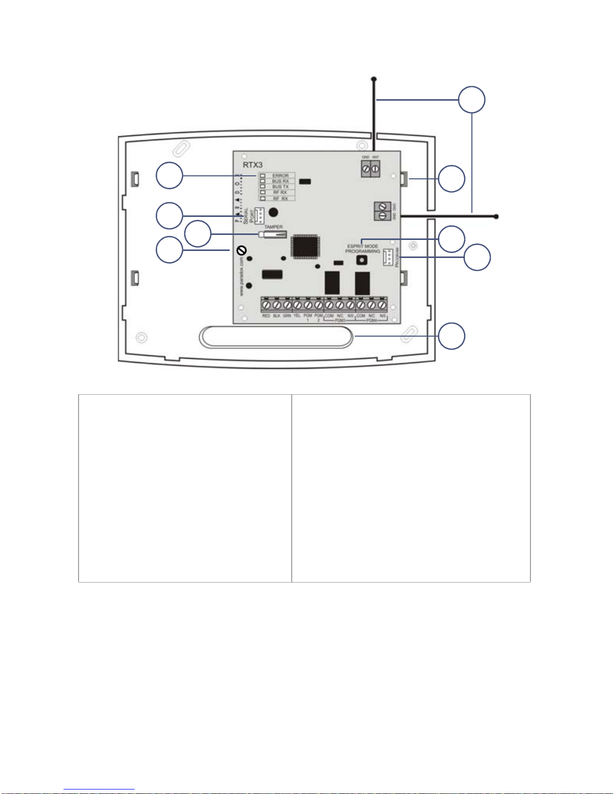
1. LED display
(see LED Feedback on page 8)
2. Firmware upgrade serial
connection (see Firmware
Upgrade on page 18)
3. Anti-tamper switch
4. PCB screw
5. Antennas
6. Mounting clips
7. Esprit Mode Programming button:
Press to enter programming mode in
Esprit mode (see Programming for
Esprit and Stand Alone on page
page 15). Also used for system reset
(see System Reset on page 7).
8. Connect the Esprit 636/646 LED
keypad to the “Program” connector
to program in Esprit and Stand Alone
mode.
9. Wiring slot
2
8
7
1
5
43
9
6

Installation Page 7
Chapter 2: Installation
1. Control panel Combus connection
NOTE: If you are using the RTX3 as a stand-alone device, connect an
external 12Vdc power supply to the RED and BLK terminals. Battery backup
is recommended.
2. If the current draw exceeds 150mA on PGM1 or PGM2, use a relay.
Connect the RTX3’s RED connector to the relay’s RED connector, and the
PGM connector (PGM1 or PGM2) to the relay’s BLK connector.
3. Connect PGM3 and PGM4 to external power supplies if you need additional
power. A PS-817 is recommended. Connect the PGM’s N/O connector to
the external power supply’s “+” connection. Connect the power supply’s “-”
connector to the device’s “-” connector. Connect the PGM’s COM connector
to the device’s “+” connector.
NOTE: Write down the serial number of all wireless modules to be used with
the RTX3. If this installation replaces another RTX3, make sure the
programming can be transferred.
System Reset
The system reset feature only functions during the first 30 seconds after RTX3
power up. In order to reset the system, press and hold the Programming button
for 5 seconds, the BUS RX LED flashes. Release the button and press it again
while the LED flashes to reset the module to its default values.
2
3
1

Page 8 Programming
LED Feedback
Chapter 3: Programming
This chapter provides programming instructions for Imperial, Spectra SP
Series, EVO, Esprit, and stand alone installations.
Programming for Imperial
When connected to an Imperial panel, all RTX3 settings are programmed using
BabyWare. For more detailed instructions on using BabyWare and
programming remotes, refer to the Imperial System Guide.
All Panels
ERROR
Problem with the module
BUS RX
Receiving from panel
BUS TX
Transmitting to panel
RF RX
Receiving wireless
RF TX
Transmitting wireless
R
G
G
G
Y
EVO and SP Series only
ERROR
BUS RX
BUS TX
Com fail: GRN/YEL
short / no data
R
ERROR
BUS RX
BUS TX
Com fail: too many
modules / wrong data
R
G
ERROR
BUS RX
BUS TX
Com fail: GRN/
YEL reversed
G
R
G
ERROR
BUS RX
BUS TX
Combus power
too low
R
Legend
R = Red
G = Green
Y = Yellow
= Off
= On
= Flashing

Programming Page 9
To program an RTX3 for an Imperial system:
1. When BabyWare is communicating with the V32 controller and an RTX3
module is connected to the Multibus, it automatically appears in the Modules
display area. To view the Modules display area, click the Modules toggle
button. Alternatively, you may wish to add a module to BabyWare before the
module is physically connected to the system. Click the Add Item button
and add the RTX3 from the Zone Expansion Modules list.
2. When the RTX3 is added to the system, double-click the module’s icon. The
RTX3 Programming window opens.
3. From the RTX3 Programming window, configure Input Setup and Input
options. Click OK.
Programming for Spectra SP Series
When connected to a Spectra SP series panel, the wireless settings are
programmed using control panel programming sections. Refer to the panel’s
Programming Guide.
NOTE: Programming for a Spectra SP series system requires K32 or K10V/H
keypads version 2.0 or higher.
NOTE: Only one RTX3 module can be connected to a Spectra SP Series
panel.
Programming for EVO
When connected to an EVO panel, the wireless settings are programmed in
Module Programming Mode.
To enter Module Programming Mode:
1. Press and hold the [0] key.
2. Enter your [INSTALLER CODE].
3. Enter section [4003].
4. Enter the module’s [SERIAL NUMBER]
5. Enter the required [DATA].
NOTE: When used without a K641 or K641R keypad, enable EVO option [1] in
section [3029].
After Programming for EVO
Program the zones, PGMs, and remotes into the EVO panel. Refer to EVO
section [3034] and RTX3 section [001]* options [2] and [3] for wireless
transmitter supervision options.
* For instructions on entering 3-digit RTX3 section numbers, see RTX3
Programming Sections for EVO on page 10.

Page 10 Programming
RTX3 Programming Sections for EVO
Section Feature Details
[001] RTX3 options
Option [1] Low battery
supervision For RTX3 version 1.5 and higher,
this option is always On
(default: On).
Option [2] Check-in supervision default: Off
Option [3] Check-insupervision
time interval Off = 24 hours (default)
On = 80 minutes
Option [4] RF Jamming
supervision default: Off
Option [5] On-board module
tamper supervision default: Off
Option [6] PGM1 initial state Off = Normally Open (default)
On = Normally Closed
Option [7] PGM2 initial state Off = Normally Open (default)
On = Normally Closed
Option [8] Transmitter tamper
signal Off = RTX3 ignores tamper signal
(default)
On = RTX3 reports tamper signal
[002] Remote control options
Option [1] REM2 Visual and
auditory feedback
compatibility
options*
Off = Old visual and auditory
feedback (Supported by
REM2 V2.00 or lower)
On = New visual and auditory
feedback (default)
(Requires REM2 V2.01 or
higher with K641 / K641R
keypads)
[030] View transmitter, remote and
PGM serial numbers To view a transmitter’s 6-digit serial
number, press and hold the
transmitter’s anti-tamper switch.
* The new visual and auditory feedback includes the following system
statuses: stay armed, instant armed and exit delay. Other status feedback has
not changed. Note that for REM2 versions 1.04 or older, stay arm, instant arm
and exit delay statuses are not supported, and a rejection beep will be heard
when the system is in these statuses.
Inhaltsverzeichnis
Beliebte Drahtloser Zugangspunkt Handbücher anderer Marken

D-Link
D-Link DWL-2100AP - AirPlus Xtreme G Bedienungsanleitung

Ubiquiti
Ubiquiti NanoStation NSM2 Bedienungsanleitung

Cisco
Cisco Aironet 1550 Series Bedienungsanleitung

Aruba
Aruba IAP-335 Bedienungsanleitung

Advantek Networks
Advantek Networks AWN-AP-54MR Bedienungsanleitung

IP-COM
IP-COM AP355 Bedienungsanleitung

Buffalo
Buffalo AirStation WLA-L11G Bedienungsanleitung

EnGenius
EnGenius EnStationACv2 Bedienungsanleitung

D-Link
D-Link DAP-3662 Bedienungsanleitung

xG Technology
xG Technology xMax CN1300 Bedienungsanleitung

Widelink
Widelink ezWave WAP-1100 Series Bedienungsanleitung

Edimax
Edimax CAP1200 Bedienungsanleitung


 Bedienungsanleitung")
