
Microchip Technology MCHPRT2 Bedienungsanleitung

ATWINC/ATWILC/ATSAMB/
ATBTLC
MCHPRT2 User Guide
Introduction
This document provides detailed information about the MCHPRT2 tool, which allows the user to easily
configure, evaluate and test an RF system. This tool simplifies the effort during the early stage of
development, regulatory certification and production testing. The MCHPRT2 tool with v1.0 is used for this
demonstration. MCHPRT2 is a Windows®-based software program.
Note: The ATWINC, ATWILC, ATBTLC, and ATSAMB denotes the following:
• ATWINC15x0
• ATWINC3400
• ATWILC1000
• ATWILC3000
• ATBTLC1000
• ATSAMB11
Features
The MCHPRT2 tool includes the following functions for the ATWINC/ATWILC and ATBTLC/ATSAMB
devices:
• Flexible Graphical User Interface (GUI) configuration Options
• Inbuilt Command Line Interpreter (CLI)
• Wi-Fi® RF Performance Evaluation
• Bluetooth® Low Energy (BLE) RF Performance Evaluation
• Continuous Wave (CW) Transmitter
• RF Frequency Offset Calibration
• e-Fuse Programming
• Register Read/Write
• Register Range Dump
• Received Signal Strength Indicator (RSSI) Reading
• Firmware (FW) Upgrade
• Gain Table Update
• Webpage Upgrade
© 2019 Microchip Technology Inc. User Guide DS50002893A-page 1

Table of Contents
Introduction......................................................................................................................1
Features.......................................................................................................................... 1
1. Prerequisite............................................................................................................... 4
1.1. Hardware Prerequisites................................................................................................................4
1.2. Software Prerequisite................................................................................................................... 5
1.3. UART/I2C Pin Details .................................................................................................................. 7
1.4. Power-Up/Down Sequence.......................................................................................................... 7
1.5. Hardware Setup......................................................................................................................... 10
2. Graphical User Interface..........................................................................................13
2.1. Wi-Fi........................................................................................................................................... 13
2.2. Bluetooth Low Energy (ATWILC3000/ATWINC3400).................................................................22
2.3. Temperature Calibration Calculator............................................................................................27
2.4. Bluetooth Low Energy (ATBTLC/ATSAMB)................................................................................27
2.5. Register......................................................................................................................................32
2.6. eFuse......................................................................................................................................... 34
2.7. Firmware Upgrade......................................................................................................................36
3. Command Line........................................................................................................ 39
3.1. Wi-Fi........................................................................................................................................... 39
3.2. Bluetooth (ATWILC3000/ATWINC3400).....................................................................................54
3.3. BLE (ATBTLC1000/ATSAMB11)................................................................................................ 65
3.4. HCI Command............................................................................................................................73
3.5. Register......................................................................................................................................76
3.6. eFuse (ATWINC/ATWILC)..........................................................................................................81
3.7. efuse ATBTLC/ATSAMB.............................................................................................................87
3.8. Firmware Upgrade......................................................................................................................89
4. Appendix A - Python® Example...............................................................................96
4.1. Example..................................................................................................................................... 96
5. Appendix B - HCI Command Tools..........................................................................98
5.1. HCI Initialization......................................................................................................................... 98
5.2. HCI Command............................................................................................................................99
5.3. UART Initialization....................................................................................................................102
5.4. Serial Port.................................................................................................................................103
6. Appendix C - Firmware Update............................................................................. 108
6.1. Firmware Update......................................................................................................................108
7. Appendix D - Erase and Program ATSAMB11.......................................................113
8. Appendix E - eFuse and MAC Address ................................................................ 114
ATWINC/ATWILC/ATSAMB/ATBTLC
© 2019 Microchip Technology Inc. User Guide DS50002893A-page 2

9. Revision History.....................................................................................................116
The Microchip Website................................................................................................ 117
Product Change Notification Service........................................................................... 117
Customer Support........................................................................................................117
Microchip Devices Code Protection Feature............................................................... 117
Legal Notice.................................................................................................................118
Trademarks..................................................................................................................118
Quality Management System.......................................................................................119
Worldwide Sales and Service......................................................................................120
ATWINC/ATWILC/ATSAMB/ATBTLC
© 2019 Microchip Technology Inc. User Guide DS50002893A-page 3

1. Prerequisite
This chapter provides the hardware and software prerequisites for using MCHPRT2 tool with the
ATWINC/ATWILC series and ATBTLC/ATSAMB series.
1.1 Hardware Prerequisites
This section provides the hardware tools that are required to test the RF system. ATWINC/ATWILC is
connected to the GUI using Aardvark™ or serial bridge. SAM-ICE™ is used to connect ATBTLC/ATSAMB
to GUI.
1.1.1 Aadvark I2C Host Adapter
Aardvark I2C/HCI Host adapter is used to interface PC via USB to I2C pins of ATWINC/ATWILC. The
same is shown in the following figure. For more information, refer to http://www.totalphase.com/products/
aardvark-i2cspi/.
Figure 1-1. Aardvark I2C/HCI Host Adapter
1.1.2 USB - UART Converter
This USB-UART converter (MCP2200) Breakout Module) will be used to interface PC to the UART DTM
interface of ATWINC3XXX, ATBTLC1000 and ATSAMB11 devices. Any generic USB-UART converter can
also be used.
Figure 1-2. USB - UART Converter
ATWINC/ATWILC/ATSAMB/ATBTLC
Prerequisite
© 2019 Microchip Technology Inc. User Guide DS50002893A-page 4

1.1.3 JTAG Emulator
The AT91SAM-ICE is a JTAG emulator designed for ARM® core based MCUs and MPUs. It is used to
program test firmware. For more information, refer to http://www.microchip.com/DevelopmentTools/
ProductDetails.aspx?PartNO=at91sam-ice
Figure 1-3. AT91SAM-ICE JTAG Emulator
1.2 Software Prerequisite
1.2.1 Serial Bridge Connection (ATWILC/ATWINC)
MCHPRT2 GUI can be operated without the Aadvark tool with the help of serial bridge application from
Atmel Studio. In the GUI, instead of I2C select UART. Enter the valid Com port, baud rate and click Init to
start evaluating the RF test system. For more information, see the Serial Bridge Application Note.
1.2.2 MCHPRT2 GUI Tool
The MCHPRT2 tool allows the user to easily configure, evaluate and test an RF system. It simplifies the
effort during the early stage of development. The later sections have a detailed explanation on how the
tool is used to test the RF system.
ATWINC/ATWILC/ATSAMB/ATBTLC
Prerequisite
© 2019 Microchip Technology Inc. User Guide DS50002893A-page 5

Figure 1-4. MCHPRT2 GUI Tool
1. Click the tab for Initialization, eFuse, Wi-Fi, BLE or Register read and write option.
2. It is a function block for the selected tab.
3. CMD command line block.
4. Com port block.
5. Device connectivity status:
– Close: Sub process "MCHPRT" is close.
– Ready: "MCHPRT" is waiting for the command.
– Processing: "MCHPRT" is running.
1.2.2.1 MCHPRT2 Software Architecture
MCHPRT2 is a C# program using MCHPRT command line function for RF test or automation test
example. The following link has an example of process function to open, send and receive the command.
https://docs.microsoft.com/en-us/dotnet/api/system.diagnostics.process?
redirectedfrom=MSDN&view=netframework-4.7.2.
The following is the architecture of MCHPRT2.
Figure 1-5. MCHPRT2
ATWINC/ATWILC/ATSAMB/ATBTLC
Prerequisite
© 2019 Microchip Technology Inc. User Guide DS50002893A-page 6

For MCHPRT2 source code contact Microchip sales.
1.3 UART/I2C Pin Details
Connect the UART or I2C to PC, and power on the ATWINC/ATWILC/ATBTLC/ATSAMB. Ensure that
ATWINC/ATWILC/ATBTLC/ATSAMB is in the right test mode with the correct pins.
The following table provides the I2C connection for ATWINC/ATWILC 1XXX and 3XXX series.
Table 1-1. I2C Connection
Connections 1XXX Module series 1XXX Chip series 3XXX Module series 3XXX Chip series
I2C Slave Data Pin 3 Pin 33 Pin 10 Pin 16
I2C Slave clock Pin 2 Pin 32 Pin 11 Pin 17
BT_TXD NA NA Pin 8 Pin 14
BT_RXD NA NA Pin 9 Pin 15
Connect the J-Link and power on the ATBTLC/ATSAMB-ZR series. Connect the BT_TXD and BT_RXD
lines to the UART input pins of an USB-UART converter.
The following table provides the J-Link connection for ATBTLC/ATSAMB series. Pin 41-49 is ground
exposed paddle; it must be soldered to system ground.
Table 1-2. J-Link Connection
Connections ATBTLC ZR
Module series
ATBTLC ZR Chip
series
ATSAMB ZR
Module series
ATSAMB ZR Chip
series
SWCLK Pin 12 Pin 35 Pin 12 Pin 35
SWDIO Pin 13 Pin 36 Pin 13 Pin 36
BT_TXD Pin 15 Pin 38 Pin 15 Pin 38
BT_RXD Pin 14 Pin 37 Pin 14 Pin 37
Note: MCHPRT/MCHPRT2/HCI_Command tools have DTR enable or disable function on UART.
For example:
SAMB11 Xpro board serial port setting is different, which only supports the following conditions:
serialport.DtrEnable = true;
serialport.Handshake = Handshake.RequestToSend;
serialport.RtsEnable = true;
In MCHPRT/MCHPRT2/hci_command tools DTR must be enabled.
1.4 Power-Up/Down Sequence
This section provides the power-up/down sequence for ATWINC/ATWILC/ATSAMB/ATBTLC.
ATWINC/ATWILC/ATSAMB/ATBTLC
Prerequisite
© 2019 Microchip Technology Inc. User Guide DS50002893A-page 7

1.4.1 Power-up/down Sequence (ATWINC/ATWILC)
The power-up/down sequence for ATWINC/ATWILC is shown in the following figure. The timing
parameters are provided in following the table.
Figure 1-6. Power-up/down Sequence (ATWINC/ATWILC)
Table 1-3. Power-up/down Sequence Timing Parameters
Parameter Min. Units Description
tA0 ms
• VBATT rise to VDDIO rise
• VBATT and VDDIO can rise simultaneously or can be tied
together. VDDIO must not rise before VBATT.
tB0 ms
• VDDIO rise to CHIP_EN rise
• CHIP_EN must not rise before VDDIO. CHIP_EN must be
driven high or low, not left floating.
tC5 ms
• CHIP_EN rise to RESETN rise
• This delay is needed because the XO clock must stabilize
before RESETN removal. RESETN must be driven high or low,
not left floating.
tA’ 0 ms
• VDDIO fall to VBATT fall
• VBATT and VDDIO can fall simultaneously or can be tied
together. VBATT must not fall before VDDIO.
tB’ 0 ms
• CHIP_EN fall to VDDIO fall
• VDDIO must not fall before CHIP_EN. CHIP_EN and RESETN
can fall simultaneously.
tC’ 0 ms
• RESETN fall to VDDIO fall
• VDDIO must not fall before RESETN. RESETN and CHIP_EN
can fall simultaneously.
ATWINC/ATWILC/ATSAMB/ATBTLC
Prerequisite
© 2019 Microchip Technology Inc. User Guide DS50002893A-page 8
It is mandatory that the ATWINC/ATWILC chip is in the right bootloader state for establishing connection
from GUI through I2C. To do that, the host MCU must power-up the ATWINC/ATWILC chip and then
perform the reset sequence as defined in the figure Power-up/down Sequence (ATWINC/ATWILC). This
is done very easily from the host MCU by calling the nm_bsp_init() and nm_bsp_reset() function. The
code snippet for the same is as shown below,
int main(void)
{/* Initialize the board. */
system_init();
/* Initialize the BSP. */
nm_bsp_init();
nm_bsp_reset();
while(1) {
}
}
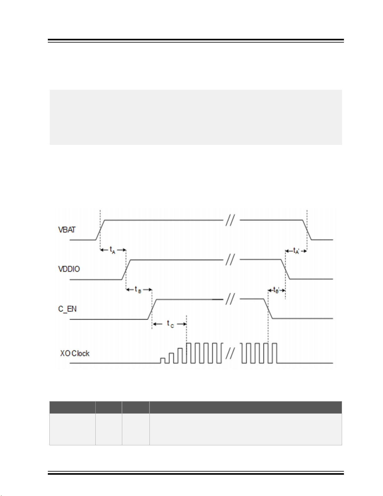
1.4.2 Power-up/down Sequence (ATBTLC/ATSAMB)
The power-up/down sequence for ATBTLC/ATSAMB is shown in the following figure. The timing
parameters are provided in following the table. For SAMB11, ensure that the steps referred in Appendix
A5 Erase and Program SAMB11 are followed before establishing connection with MCHPRT2 GUI.
Figure 1-7. Power-up/down Sequence (ATBTLC/ATSAMB)
Note: Pull the A0_GPIO_0 (Wake Up pin) High during the test.
Table 1-4. Power-up/down Sequence Timing Parameters
Parameter Min. Units Description
tA0 ms
• VBAT rise to VDDIO rise
• VBAT and VDDIO can rise simultaneously or can be tied
together.
ATWINC/ATWILC/ATSAMB/ATBTLC
Prerequisite
© 2019 Microchip Technology Inc. User Guide DS50002893A-page 9

...........continued
Parameter Min. Units Description
tB0 ms
• VDDIO rise to C_EN rise
• C_EN must not rise before VDDIO. C_EN must be driven high
or low, not left floating.
tC10 ms C_EN rise to 31.25 kHz (2 MHz/64) oscillator stabilizing
tA’ 0 ms
• VDDIO fall to VBAT fall
• VBAT and VDDIO can fall simultaneously or can be tied
together.
tB’ 0 ms
• C_EN fall to VDDIO fall
• C_EN must fall before VDDIO. C_EN must be driven high or
low, not left floating.
1.5 Hardware Setup
The following figures illustrate the block diagram of the test setup using ATWINC.
Figure 1-8. ATWINC1500 Hardware Setup
ATWINC/ATWILC/ATSAMB/ATBTLC
Prerequisite
© 2019 Microchip Technology Inc. User Guide DS50002893A-page 10
Inhaltsverzeichnis


