
Napa 2562 Bedienungsanleitung

CTI 2562 Quick Start Guide Rev 07-20-2021
1
2562 QUICK START GUIDE
CTI P/Ns: 2562 Quick Start Guide: 062-00348-010
Summary:The 2562 is designed to translate a digital word from the programmable logic controller (PLC)
into an equivalent analog voltage and/or current output signal. Configuration of the module, taken from
the full-length Installation and Operation Guide’s Chapter 2, is as follows. Refer to the 2562 Installation
and Operation Guide for more detailed information on this module. The IOG may be downloaded from
our website at www.controltechnology.com.
2.3. Configuring the Module for Operation
The 2562 must be configured for voltage output range, unipolar or bipolar mode, offset mode, and
zero/last value mode before wiring the output connectors and inserting the module into the I/O base. As
shipped, all output channels are configured for the 5V output range, unipolar outputs, disabled offset
mode, and last value output at power up.
Configuring the 2562 for operation consists of the following steps (notations in parenthesis are actual
printed board titles):
1. Selecting 0-5V (5V) or 0-10V (10V) output voltage range for each channel.
2. Selecting unipolar (UNI) or bipolar (BI) mode for each output channel.
3. Setting DIP switches for each channel to match the hardware configuration.
4. Selecting offset scaling enabled (EN) or disabled (DIS) for the entire module.
5. Selecting either zero (ZERO) or last value (LAST VALUE) at power up for the module.
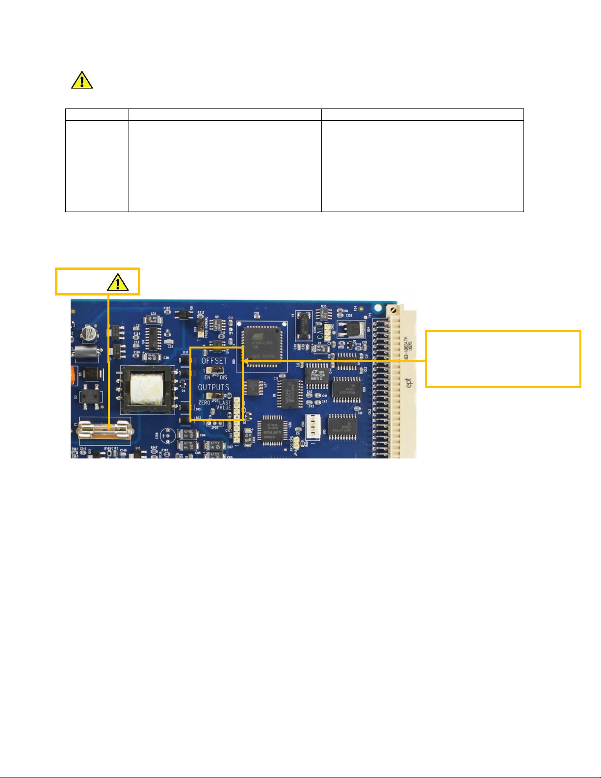
Figure 1 Configuring the Module
(Jumpers and DIP Switches shown in default shipping position.)
CTI 2562 Quick Start Guide Rev 07-20-2021
2
Fuse F1
Clause
English
French
9.7.1
WARNING –EXPLOSION HAZARD. DO NOT
REMOVE OR REPLACE WHILE CIRCUIT IS LIVE
UNLESS THE AREA IS FREE OF IGNITIBLE
CONCENTRATIONS.
AVERTISSEMENT –RISQUE D’EXPLOSION. NE
PAS RETIRER NI REMPLACER PENDANT QUE LE
CIRCUIT EST SOUS TENSION À MOINS QUE
L’EMPLACEMENT NE SOIT EXEMPT DE
CONCENTRATIONS INFLAMMABLES.
9.8.1
WARNING –EXPLOSION HAZARD. DO NOT
REMOVE OR REPLACE FUSE WHEN
ENERGIZED.
AVERTISSEMENT –RISQUE D’EXPLOSION. NE
JP40 Offset Enable/Disable
Jumper
JP 25 Zero/Last Value Jumper
CTI 2562 Quick Start Guide Rev 07-20-2021
3
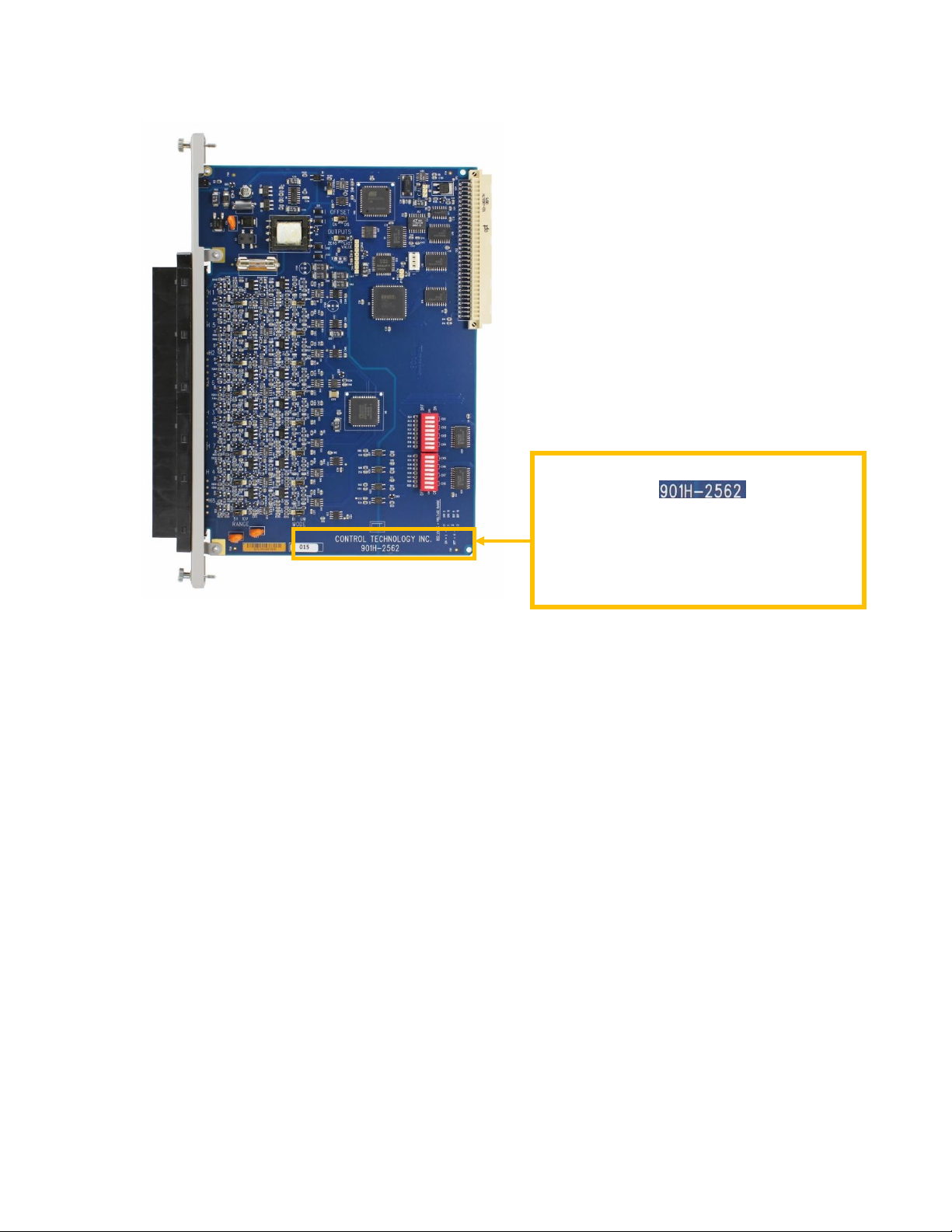
Figure 2 F1 and JP25 and JP40 Locations
The letter “H” designates the printed circuit
board Revision:
Board Revisions are done to improve
product manufacturability and sometimes
improve product functionality. Always
check your board Rev and the manual for
any differences.
CTI 2562 Quick Start Guide Rev 07-20-2021
4
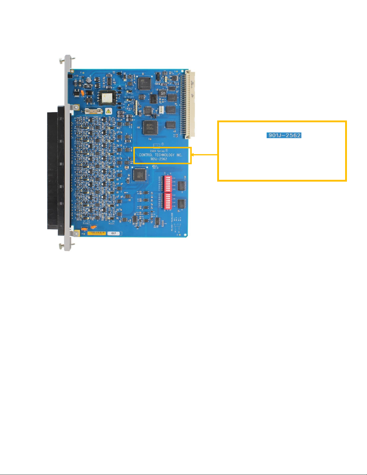
Figure 3 Rev J Identifier Location
The letter “J” designates the printed circuit
board Revision: Board
Revisions are done to improve product
manufacturability and sometimes improve
product functionality. Always check your
board Rev and the manual for any
differences.
CTI 2562 Quick Start Guide Rev 07-20-2021
5
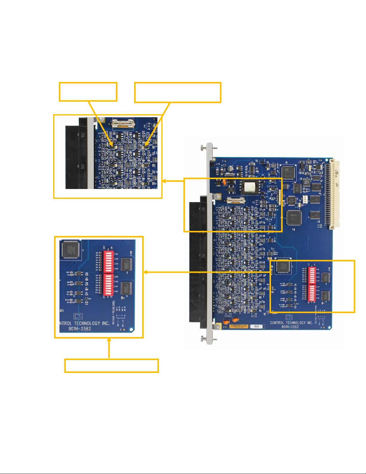
Figure 4 Channel Voltage and Range Selection
Channel 5V/10V
Selection Jumper
Channel UNIPOLAR/BIPOLAR
Selection Jumper
Range Selection DIP Switches

CTI 2562 Quick Start Guide Rev 07-20-2021
6
Channel
Number
Voltage Range
Jumper
Jumper Position
5V or 10V
Unipolar/Bipolar
Jumper
Jumper Position
Uni or Bi
1
JP28
5V
JP24
UNI
2
JP6
5V
JP5
UNI
3
JP2
5V
JP1
UNI
4
JP12
5V
JP11
UNI
5
JP8
5V
JP7
UNI
6
JP4
5V
JP3
UNI
7
JP10
5V
JP9
UNI
8
JP14
5V
JP13
UNI
All
Channels
Offset Mode
Jumper
Offset Mode
Jumper Position
Outputs at Power
Up Jumper
Outputs at Power Up
Jumper Position
1-8
JP40
DISABLED
JP25
LAST VALUE
Figure 5 Jumper Configuration as Shipped
2.3.1. Selecting Either 5 VDC or 10 VDC Range for Each Channel
The 2562 is capable of supporting Unipolar or Bipolar applications with an output range of 0 to +5 VDC,
0 to +10 VDC, -5 to +5 VDC or -10 to +10 VDC. For each channel a hardware jumper selects the range
for that output circuit. Select 5 VDC range for all current applications. As shipped, the 5V range is
selected.
2.3.2. Selecting Unipolar or Bipolar Output
Each output channel on the 2562 supports Unipolar or Bipolar output operation. Hardware jumpers select
operation of the output. Select Bipolar for applications that drive the outputs from -5 to +5 VDC, -10 to
+10 VDC, or -20 to +20 mA. As shipped, Unipolar range is selected.
CTI 2562 Quick Start Guide Rev 07-20-2021
7
2.3.3. Setting DIP Switches to Match the Hardware Selections
Once the hardware jumpers are selected this information needs to be reported to the microcomputer. The
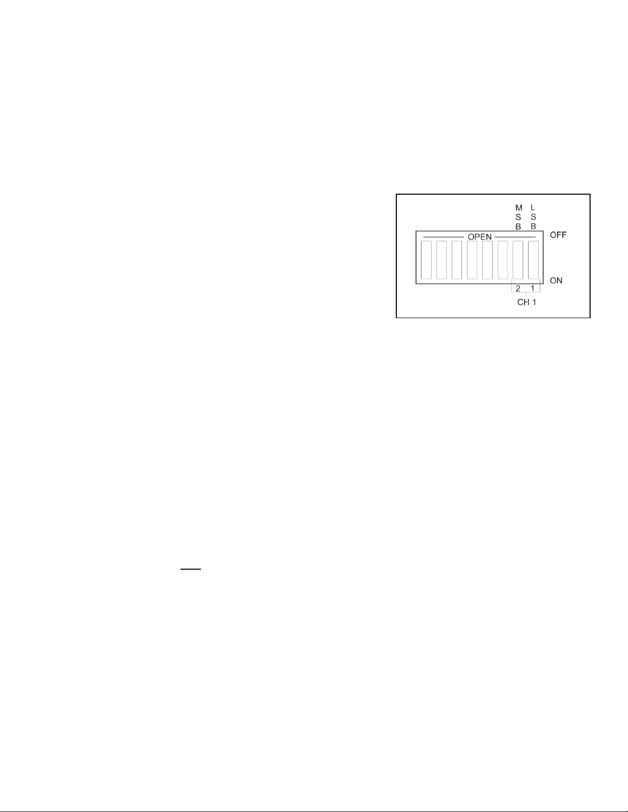
information is reported via DIP switches SW1 and SW2. Each output channel uses 2 switches with a
BCD code to indicate the state of the hardware jumpers. As shipped, Unipolar 5VDC is selected.
2 (MSB) 1 (LSB) Range
OFF OFF Unipolar 5VDC
OFF ON Unipolar 10VDC
ON OFF Bipolar 5VDC
ON ON Bipolar 10VDC
2.3.4. Selecting Automatic Offset Mode for the Entire Module
Some applications require an Offset mode of 4-20 mA or 1-5 VDC. The SIMATIC® TI PLC can adjust
an output loop calculation to provide an offset output. If the application does not use the PID control
block then the processing must be done in relay ladder logic. The 2562 can perform this offset calculation
and output an offset signal independent of the PLC. Selecting this function with JP40 causes all eight
outputs to be scaled. Move the jumper to the ENABLED position to select this function. As shipped the
module offset is DISABLED.
2.3.5. Selecting Either Zero or Last Value Output at Power Up
Upon power up of the base power, the 2562 allows the user to choose between either a zero output value
or last output value when transitioning to the next update. A hardware JP25 jumper setting sets the entire
module for the mode chosen. Section 2.9. Power Cycling explains the details of each selection. As
shipped the module power up mode is LAST VALUE.
Note: this jumper only has effect when power is lost from the base.
2.3.6. Jumper Settings for Future Reference
See Appendix B. Jumper Settings Log Sheet to record any changes to the module’s factory jumper
settings.

CTI 2562 Quick Start Guide Rev 07-20-2021
8
2.4. Inserting the Module into the I/O Base
When the module is fully seated in the slot, captive screws at the top and bottom will hold the module in
place. To remove the module from the I/O base, loosen these captive screws, and then remove the module
from the I/O base. Do not damage the edge connector at the back of the module when inserting or
removing the module.
2.5. Wiring the Output Connector
Output signals are provided through a connector assembly located on the front of the module. The
connector assembly consists of a header attached to the printed circuit card and a mating removable screw
terminal plug. Field Wiring is connected through the removable screw terminal plug.
Figure 6 Output Screw Terminal Plug Wiring
2.5.1. Connecting Voltage Output Wiring
First, loosen the wire locking screws on the output screw terminal plug. For voltage output circuits,
connect the signal wire to the VO screw terminal, and the return wire to the Return (channel ground)
screw terminal. Insert the wires in the appropriate holes next to the screws. When the wires are inserted,
tighten the screws. Repeat this procedure for the remaining voltage output channels.

CTI 2562 Quick Start Guide Rev 07-20-2021
9
2.5.2. Connecting Current Output Wiring
For current output circuits, connect the signal wire to the IO screw terminal, and the return wire to the
Return (channel ground) screw terminal. Insert the wires in the appropriate holes next to the screws.
When the wires are inserted, tighten the screws. Repeat this procedure for the remaining current output
channels.
2.5.3. Connecting the Shield Wiring
See the diagram below that describes cable grounding and chassis ground.
Figure 7 Connecting the Shield Wiring
Note:
A static drain is recommended on the 2562 to prevent a static charge buildup from occurring. A 10K to
1M resistor from any analog common to earth ground (chassis ground is front panel output connector
pins D4 or D8) is sufficient for protection.
CTI 2562 Quick Start Guide Rev 07-20-2021
10
2.6. Inserting the Screw Terminal Plug
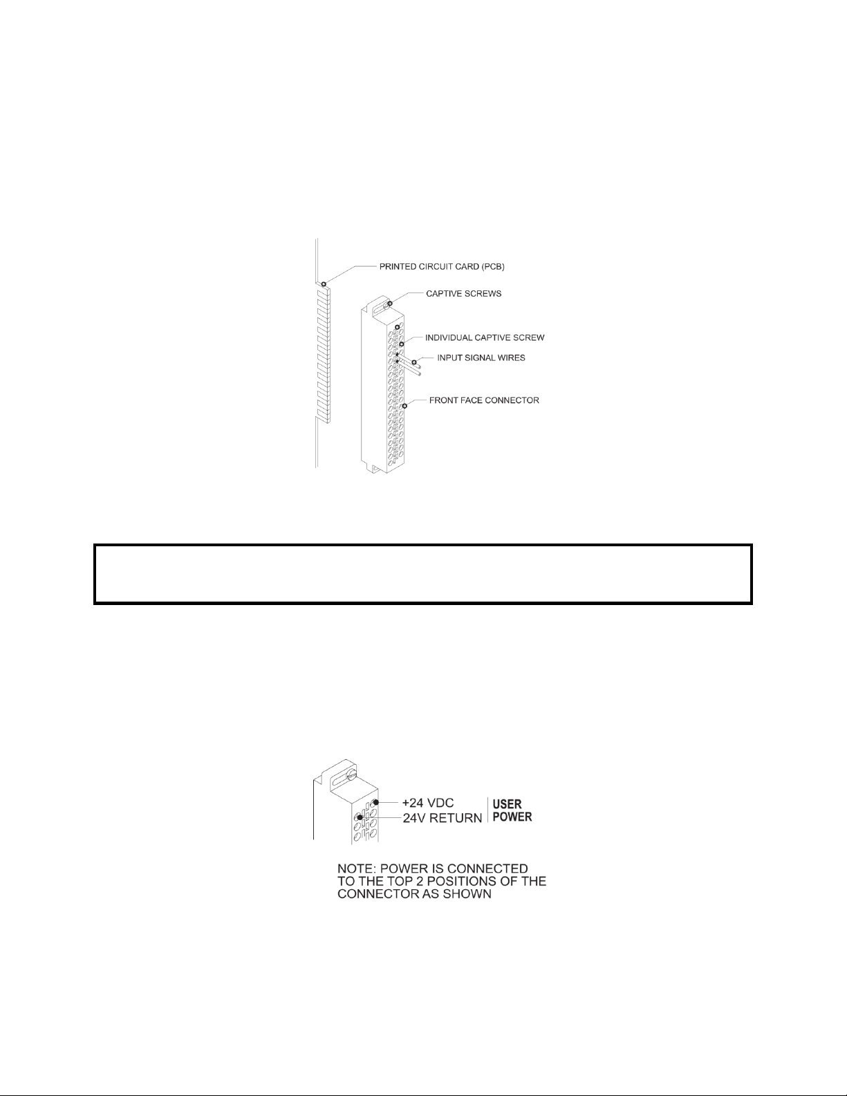
When all the output signal wires are connected to the screw terminal plug, carefully insert the plug into its
header. Both the plug and header are keyed to prevent reverse wiring. When the screw terminal is fully
inserted onto the header, use the captive screws to secure the plug to the front panel.
Figure 8 Attaching the Screw Terminal Plug
WARNING:
Always remove power from the I/O base before inserting a module to minimize the risk of
injury or damage to equipment. Never insert a module into a powered I/O base.
2.7. Connecting the 24 VDC User Power Supply
The power supply is connected to the top 2 positions of the top connector on the front of the module as
shown in Figure 2.7 below. Be sure to check that the 24V fuse is present and intact. See Chapter 3
Troubleshooting recommendations for replacement fuses.
Figure 9 Power Supply Connection
Inhaltsverzeichnis
Beliebte E/A-System Handbücher anderer Marken

WAGO
WAGO 750-344 Bedienungsanleitung

Teknim
Teknim TWM-1887 Bedienungsanleitung

Intelligent Appliance
Intelligent Appliance IA-2662-E Bedienungsanleitung

BERGHOF
BERGHOF ECC DIO 16/16 Bedienungsanleitung

Advantech
Advantech PCM-27J3AU Installations- und Betriebshandbuch

Festo
Festo CP-E08-M12-CL Bedienungsanleitung


