
National Instruments NI 9467 Bedienungsanleitung
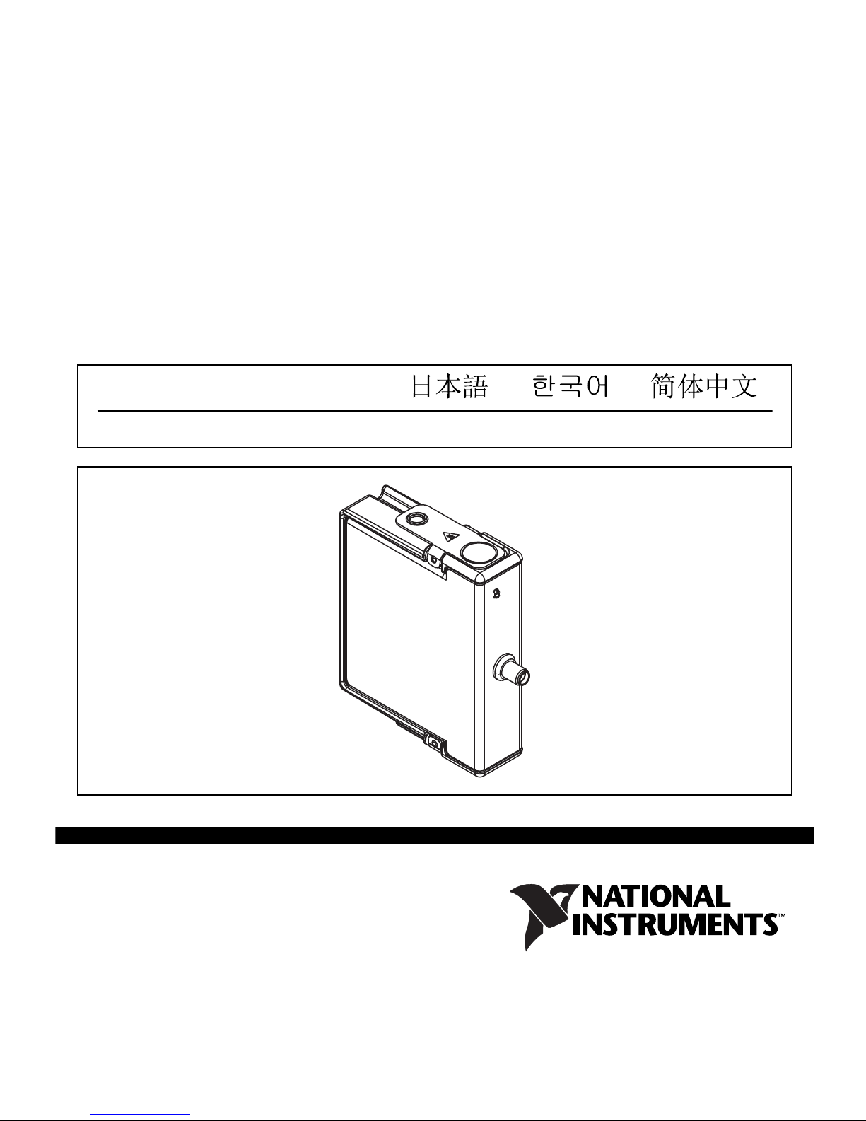
OPERATING INSTRUCTIONS AND SPECIFICATIONS
NI 9467
C Series GPS Synchronization Module
ni.com/manuals
DeutschFrançais
NI 9467 Operating Instructions and Specifications 2 ni.com
This document describes how to use the NI 9467 and includes
specifications. Visit ni.com/info and enter rdsoftwareversion
to determine which software youneed for the modules youare using.
For information about installing, configuring, and programming the
system, refer to the system documentation. Visit ni.com/info and
enter cseriesdoc for information about C Series documentation.
Note The safety guidelines and specifications in this
document are specific to the NI 9467. The other
components in the system might not meet the same safety
ratings and specifications. Refer to the documentation for
each component in the system to determine the safety
ratings and specifications for the entire system. Visit
ni.com/info and enter cseriesdoc for information
about C Series documentation.
Safety Guidelines
Caution Do not operate the NI 9467 in a manner not
specified in the user manual or operating instructions.
Product misuse can result in a hazard. Youcan
compromise the safety protection built into the product if
the product is damaged in any way. If the product is
damaged, return it to National Instruments for repair.
© National Instruments 3 NI 9467 Operating Instructions and Specifications
Hot Surface This icon denotes that the component may be
hot. Touching this component may result in bodily injury.
Safety Guidelines for Hazardous Locations
The NI 9467 is suitable for use in Class I, Division 2, Groups A, B,
C, D, T4 hazardous locations; Class I, Zone 2, AEx nA IIC T4, and
Ex nA IIC T4 hazardous locations; and nonhazardous locations
only. Follow these guidelines if youare installing the NI 9467 in a
potentially explosive environment. Not following these guidelines
may result in serious injury or death.
Caution Do not disconnect I/O-side wires or connectors
unless power has been switched off or the area is known
to be nonhazardous.
Caution Do not remove modules unless power has been
switched off or the area is known to be nonhazardous.
Caution Substitution of components may impair
suitability for Class I, Division 2.
Caution For Division 2 and Zone 2 applications, install
the system in an enclosure rated to at least IP 54 as
defined by IEC 60529 and EN 60529.

NI 9467 Operating Instructions and Specifications 4 ni.com
Special Conditions for Hazardous Locations Use in Europe
This equipment has been evaluated as Ex nA IIC T4 equipment
under DEMKO Certificate No. 07 ATEX 0626664X. Each module
is marked II 3G and is suitable for use in Zone 2 hazardous
locations, in ambient temperatures of –40 °C ≤Ta ≤70 °C. If you
are using the NI 9467 in Gas Group IIC hazardous locations, you
must use the device in an NI chassis that has been evaluated as
Ex nC IIC T4, EEx nC IIC T4, Ex nA IIC T4, or Ex nL IIC T4
equipment.
Electromagnetic Compatibility Guidelines
This product was tested and complies with the regulatory
requirements and limits for electromagnetic compatibility (EMC)
stated in the product specifications. These requirements and limits
provide reasonable protection against harmful interference when
the product is operated in the intended operational electromagnetic
environment.
This product is intended for use in industrial locations. However,
harmful interference may occur in some installations, when the
product is connected to a peripheral device or test object, or if the
product is used in residential or commercial areas. To minimize
interference with radio and television reception and prevent
© National Instruments 5 NI 9467 Operating Instructions and Specifications
unacceptable performance degradation, install and use this product
in strict accordance with the instructions in the product
documentation.
Furthermore, any modifications to the product not expressly
approved by National Instruments could void your authority to
operate it under your local regulatory rules.
Caution To ensure the specified EMC performance,
operate this product only with shielded cables and
accessories.
Special Conditions for Marine Applications
Some products are Lloyd’s Register (LR) Type Approved for
marine (shipboard) applications. To verify Lloyd’s Register
certification for a product, visit ni.com/certification and
search for the LR certificate, or look for the Lloyd’s Register mark
on the product label.
Caution In order to meet the EMC requirements for
marine applications, install the product in a shielded
enclosure with shielded and/or filtered power and
input/output ports. In addition, take precautions when

NI 9467 Operating Instructions and Specifications 6 ni.com
designing, selecting, and installing measurement probes
and cables to ensure that the desired EMC performance is
attained.
Overview of the NI 9467
The NI 9467 is a stationary GPS timing module for C Series
platforms. It provides accurate timing and geographic location
information to the C Series host, which enables synchronization of
C Series systems.
At start-up, the NI 9467 automatically begins determining its
location through a process known as self-survey. During the
self-survey, the module computes a location fix every second and
averages the locations at the end to obtain a more accurate location.
After the self-survey, the NI 9467 no longer computes new location
fixes; it uses its known location and satellite signals to generate
accurate timing signals.
Start-Up Behavior
Like all GPS receivers, the NI 9467 requires GPS satellite
ephemeris and almanac data to compute accurate time and
location. The ephemeris is detailed orbital information about each
© National Instruments 7 NI 9467 Operating Instructions and Specifications
satellite (where each satellite is expected to be at a given time). The
almanac data describes the general health of each satellite (for
example, the receiver must not use signals from satellites marked
as unhealthy) and contains coarse orbit information. The GPS
satellites broadcast the ephemeris and almanac data every
30 seconds. Therefore, it usually takes approximately 30 seconds
for it to receive the ephemeris and almanac data and start
computing location and timing fixes.
Status LED
The NI 9467 has a front panel LED to indicate status. The
following table describes the meaning of each LED pattern.
Conditions LED state
Normal operation Solid green
Performing survey Blinking green
Not enough or no satellites Blinking yellow
Antenna error (no antenna or over-current) Solid yellow
Unconfigured Off
NI 9467 Operating Instructions and Specifications 8 ni.com
Note Although the module may not detect the presence
of very low-power GPS antennas, it can still function
correctly. Note that the LED and software may report
antenna error under these conditions, and if the current
consumed is close to the detection threshold the LED
may flicker. Refer to the Specifications section for more
details.
Connecting the NI 9467
The NI 9467 has one SMA female connector on its front panel for
a GPS active antenna. The connector provides a DC voltage to
power the antenna and also serves as input for the GPS RF signal.
Antenna Installation
Caution National Instruments recommends using a
lightning arrester in line with the GPS antenna
installation to protect the NI 9467 and the C Series
system from possible damage and operators from injury
in the event of lightning.
The embedded GPS receiver in the NI 9467 requires signals from
several satellites to compute accurate timing and location. The

© National Instruments 9 NI 9467 Operating Instructions and Specifications
more satellites available to the receiver, the more accurately it can
determine time and location. Therefore, the antenna location
should be such that it receives signals from the greatest number of
satellites possible. As the number of satellites visible to the antenna
decreases, the synchronization performance may also decrease.
Choose the antenna location so that the antenna has a clear view of
the sky. There is no strict definition for a clear view of the sky, but
a suitable guideline is that the GPS antenna should have a straight
line of sight to the sky in all directions (360°) down to an imaginary
line making a 30° angle with the ground. Locations far from trees
and tall buildings that could block or reflect GPS satellite signals
are best.
Maximum Cable Length
Maximum cable length depends on the GPS antenna gain and the
cable’s loss per unit of distance. National Instruments recommends
a GPS signal strength of between –135 dBm and –120 dBm at the
NI 9467 SMA input. GPS signal strength on the Earth’s surface is
typically –130 dBm. Targeting a signal strength of –125 dBm at the
SMA input, youcan compute the maximum cable length as:
Max_cable_loss = –130 dBm + antenna_gain – (–125 dBm)
Max_cable_length = Max_cable_loss /
(loss_per_unit_of_distance)

NI 9467 Operating Instructions and Specifications 10 ni.com
For example, if youuse an active antenna with gain of 28 dB and
RG-58 cable, which has a rated loss at 1.5 GHz of about 0.8 dB/m
(24.5 dB/100 ft), the maximum cable length youcould use is:
Max_cable_loss = –130 dBm + 28 dB – (–125 dBm) = 23 dB
Max_cable_length = 23 dB / (0.8 dB/m) ≈29 m
Sleep Mode
This module supports a low-power sleep mode. Support for sleep
mode at the system level depends on the chassis that the module is
plugged into. Refer to the chassis manual for information about
support for sleep mode. If the chassis supports sleep mode, refer to
the software help for information about enabling sleep mode. Visit
ni.com/info and enter cseriesdoc for information about
C Series documentation.
Typically, when a system is in sleep mode, youcannot
communicate with the modules. In sleep mode, the system
consumes minimal power and may dissipate less heat than it does
in normal mode. Refer to the Specifications section for more
information about power consumption and thermal dissipation.
Andere Handbücher für NI 9467
1
Inhaltsverzeichnis
Andere National Instruments GPS Handbücher


