Network Electronics DA-HDSDI Bedienungsanleitung

Rev. 4
Network Electronics ASA, P.O.Box 1020, N-3204 Sandefjord, Norway. Tel.: +47 33 48 99 99 – Fax: +47 33 48 99 98
USER MANUAL
DA-HDSDI
Multi Rate HD-SDI Distribution Amplifier
Network Electronics ASA
Thorøya
N-3204 Sandefjord, Norway
Phone: +47 33 48 99 99
Fax: +47 33 48 99 98
e-mail: [email protected]
www.network-electronics.com
E-mail: support@network-electronics.com – Web: http://www.network-electronics.com/
Technical specifications are subject to be changed without notice.
1

DA-HDSDI Rev. 4
DATE: 05 October 2007
Network Electronics ASA, P.O.Box 1020, N-3204 Sandefjord, Norway. Tel.: +47 33 48 99 99 – Fax: +47 33 48 99 98
E-mail: support@network-electronics.com – Web: http://www.network-electronics.com/
Technical specifications are subject to be changed without notice.
2
Revision history
The latest version is always available in pdf-format on our web-site:
http://www.network-electronics.com/
Current revision of this document is the uppermost in the table below.
Revision Replaces Date Change Description
4 3 2007-10-05 Added Materials Declaration and EFUP
3 2 11.10.05 Specification update
2 1 14.06.04 Update of chapter 4.
1 0 25.04.03 Corrected printing errors
0 B 23.04.03 First release
B A 07.04.03 Preliminary version 2
A 19.02.03 Preliminary version

DA-HDSDI Rev. 4
DATE: 05 October 2007
Network Electronics ASA, P.O.Box 1020, N-3204 Sandefjord, Norway. Tel.: +47 33 48 99 99 – Fax: +47 33 48 99 98
E-mail: support@network-electronics.com – Web: http://www.network-electronics.com/
Technical specifications are subject to be changed without notice.
3
Index
1. General......................................................................................................................................................4
2. Specifications............................................................................................................................................5
3. Format Configuration .............................................................................................................................6
3.1 Configuration Examples ......................................................................................................................7
4. Connector module....................................................................................................................................8
4.1 Mounting the connector module. .........................................................................................................8
5. Module status ...........................................................................................................................................9
5.1 GPI ALARM – Module Status Outputs ................................................................................................9
5.2 Front Panel - Status Monitoring .......................................................................................................10
Declaration of conformity with CE..........................................................................................................11
General environmental requirements for Network flashlink®equipment...........................................11
Product Warranty .....................................................................................................................................12
Materials declaration and recycling information ...................................................................................13
Materials declaration ................................................................................................................................13
Environmentally-friendly use period.......................................................................................................13
Recycling information ...............................................................................................................................14

DA-HDSDI Rev. 4
DATE: 05 October 2007
Network Electronics ASA, P.O.Box 1020, N-3204 Sandefjord, Norway. Tel.: +47 33 48 99 99 – Fax: +47 33 48 99 98
1. General
The flashlink ® DA-HDSDI is a multi bit-rate distribution amplifier module providing high performance
media distribution for various signal formats from 19.4Mbps up to 1485Mbps. The unit can be configured
to do cable equalising and reclocking of SMPTE 292M and SMPTE 259M signal formats.
The input typically provides an automatic cable equaliser for up to 100 metres of cable (Belden 1694A at
1485Mbps) with 6 re-clocked outputs. The DA-HDSDI will detect HD and SD rates and automatically
switch to correct output slew-rate. The re-clocker supports the bit-rates; 143, 177, 270, 360, 540 and
1485Mbps. For other rates, the re-clocker automatically switches to bypass mode, and the DA-HDSDI
will work as a non-reclocking distribution amplifier with cable equaliser. The DA-HDSDI also has a
special DVB-ASI mode, enabling all possible rates including empty transport streams with only K28.5
padding packets. 3 of the outputs are non-inverting and suitable for DVB-ASI.
The DA-HDSDI is designed for all distribution purposes in studio, duplication and Broadcast
applications.
Figure 1 – DA-HDSDI Multi Bit-Rate Distribution Amplifier
E-mail: support@network-electronics.com – Web: http://www.network-electronics.com/
Technical specifications are subject to be changed without notice.
4

DA-HDSDI Rev. 4
DATE: 05 October 2007
Network Electronics ASA, P.O.Box 1020, N-3204 Sandefjord, Norway. Tel.: +47 33 48 99 99 – Fax: +47 33 48 99 98
E-mail: support@network-electronics.com – Web: http://www.network-electronics.com/
Technical specifications are subject to be changed without notice.
5
2. Specifications
Electrical Input
Data rate NRZ: 19.4 to 1485 Mbps
Equalisation: Automatic
Cable equaliser and reclocker can be bypassed to
support bitrates down to 1Mbps.
Impedance: 75 ohm
Return loss: >15dB @ 1485MHz
Signal level: nom. 800mV
Apx. 200mV min. when equaliser switched to Bypass
Connector: BNC
Electrical Output
Number of outputs: 6
Connector: BNC
Impedance: 75 ohm
Return loss: >15dB, acc. to ITU-R BT.1120-3
Jitter: max 0.2UI
Peak to peak signal level: 0.8V ±0.1V
Signal polarity 3 non inverting,
3 inverting
Features
Re-clocking: Automatic SD / HD detection
Automatic output slew rate adjustment according to
SMPTE-259M / SMPTE 292M
Selectable loop bandwidth
Low: HD = 1.5MHz, SD = 500kHz
High: HD = 3MHz, SD = 1MHz
Supported clock rates: 143, 177, 270, 360, 540 and 1485Mbps
Input equalizer: Eq. bypass for non-video formats or low bit rates
Electrical
Power: +5V DC / 3W Max.
Control: Control system for access to setup and module status
with BITE (Built-In Test Equipment) for use with GYDA
Control System
Supported standards
SMPTE: SMPTE292M, SMPTE259M, SMPTE297M, SMPTE305M,
SMPTE310M
DVB-ASI: EN50083-9
AES: AES-3id (with EQ and RCL switched off)

DA-HDSDI Rev. 4
DATE: 05 October 2007
Network Electronics ASA, P.O.Box 1020, N-3204 Sandefjord, Norway. Tel.: +47 33 48 99 99 – Fax: +47 33 48 99 98
3. Format Configuration
The DA-HDSDI supports a number of different formats. The correct configuration can either be set with
a DIP switch or with the GYDA Control System. The layout of DA-HDSDI is shown in the drawing
below with the DIP switch to the upper left position.
Figure 2 – DA-HDSDI board layout.
DIP switch configuration must be set according to the table below:
Switch # Label Function DIP=OFF Function DIP=ON Comment
1 ARB Output muted when
reclocker not in lock
Automatic Reclocker Bypass.
Output never muted
Output mute
2 EQM Equaliser forced not to
mute
Automatic muting of equaliser
when signal strength is to low
Input mute
3 RCL Reclocker Bypass Reclocker ON Reclocker mode
4 EQ Cable equaliser Bypass Cable equaliser ON Equaliser mode
5 ASI SDI 177Mbps Reclocker
support
DVB-ASI Reclocker support ASI mode
6 SLL Slew-rate override. Always
high rate selected
Slew-rate limitation
automatically adjusted. SMPTE
292M and 259M
Slew-rate select
7 BWL Reclocker loop-bandwidth
high
Reclocker loop-bandwidth low Loop bandwidth
select
8 OVR GYDA control
Config. with GYDA
Override GYDA control
Config. with DIP switch
Select GYDA
config. mode
All DIP switches are off when pointing towards the release handle.
When the default setting is selected, all clock rates for HD-SDI, SDI and DVB-ASI are automatically
configured by the module itself.
E-mail: support@network-electronics.com – Web: http://www.network-electronics.com/
Technical specifications are subject to be changed without notice.
6

DA-HDSDI Rev. 4
DATE: 05 October 2007
Network Electronics ASA, P.O.Box 1020, N-3204 Sandefjord, Norway. Tel.: +47 33 48 99 99 – Fax: +47 33 48 99 98
3.1 Configuration Examples
Typical configurations for DA-HDSDI:
Figure 3 – Default; HD-SDI, SDI and DVB-ASI
Figure 4 – Transparent Mode with equalisation and no reclocking
Figure 5 – AES3id compatible and Transparent Mode without equalisation and reclocking
E-mail: support@network-electronics.com – Web: http://www.network-electronics.com/
Technical specifications are subject to be changed without notice.
7

DA-HDSDI Rev. 4
DATE: 05 October 2007
Network Electronics ASA, P.O.Box 1020, N-3204 Sandefjord, Norway. Tel.: +47 33 48 99 99 – Fax: +47 33 48 99 98
4. Connector module
The DA-HDSDI has a dedicated connector module: DA-SDI-C1. This module is mounted at the rear of
the sub-rack. The module is shown in figure 6.
Figure 6 - Overview of the DA-SDI-C1 connector module
The electrical input signal is connected to the IN BNC and the electrical outputs are connected to the O1
to O6 BNC. Please note that O2, O4 and O6 has an inverted signal, so formats like DVB-ASI can not use
be used on these outputs.
Unused outputs should be terminated with 75 ohm.
4.1 Mounting the connector module.
The details of how the connector module is mounted, is found in the user manual for the sub-rack frame
FR-2RU-10-2.
This manual is also available from our web site: http://www.network-electronics.com/
E-mail: support@network-electronics.com – Web: http://www.network-electronics.com/
Technical specifications are subject to be changed without notice.
8

DA-HDSDI Rev. 4
DATE: 05 October 2007
Network Electronics ASA, P.O.Box 1020, N-3204 Sandefjord, Norway. Tel.: +47 33 48 99 99 – Fax: +47 33 48 99 98
5. Module status
The status of the module can be monitored in three ways.
1. GYDA System Controller (optional).
2. GPI at the rear of the sub-rack.
3. LED’s at the front of the sub-rack.
Of these three, the GPI and the LED’s are mounted on the module itself, whereas the GYDA System
Controller is a separate module giving detailed information on the card status. The functions of the GPI
and the LED’s are described in sections 5.1 and 5.2. The GYDA controller is described in a separate user
manual.
5.1 GPI ALARM – Module Status Outputs
These outputs can be used for wiring up alarms for third party control systems. The GPI outputs are open
collector outputs, sinking to ground when an alarm is triggered. The GPI connector is shown in figure 7.
Electrical Maximums for GPI outputs
Max current: 100mA
Max voltage: 30V
DA-HDSDI module GPI pinning:
Signal Name Pin # Mode
Status General error status for the module. Pin 1 Open Collector
Rate Rate HD Pin 2 Open Collector
LOS Los Of Signal Pin 3 Open Collector
LOCK Reclocker in Lock Pin 4 Open Collector
Ground 0 volt pin Pin 8 0V.
Figure 7 - GPI Outlet
E-mail: support@network-electronics.com – Web: http://www.network-electronics.com/
Technical specifications are subject to be changed without notice.
9

DA-HDSDI Rev. 4
DATE: 05 October 2007
Network Electronics ASA, P.O.Box 1020, N-3204 Sandefjord, Norway. Tel.: +47 33 48 99 99 – Fax: +47 33 48 99 98
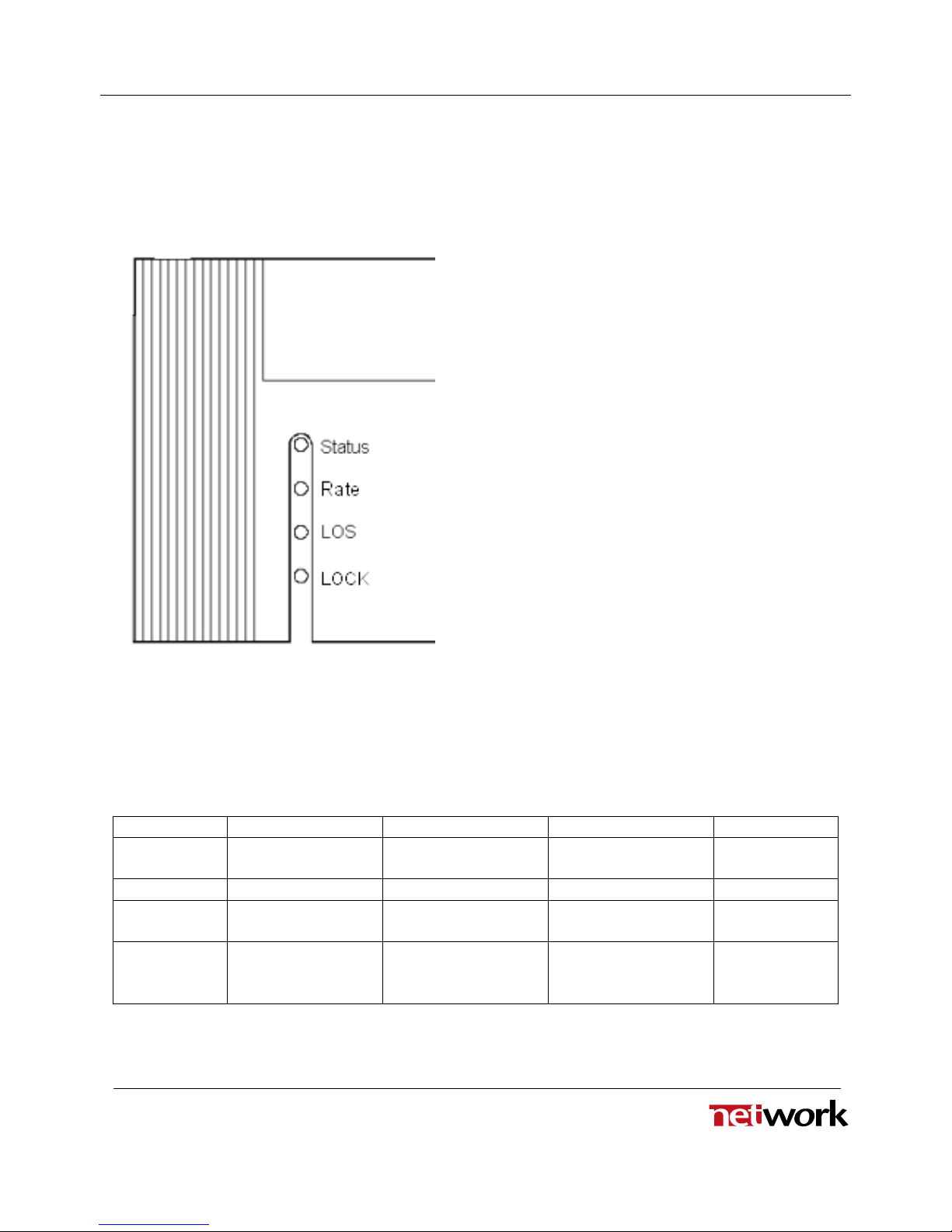
5.2 Front Panel - Status Monitoring
The status of the module can be easily monitored visually by the LED’s at the front of the module. The
LED’s are visible through the front panel as shown in figure 8 below.
(Text not printed on the front panel).
Figure 8 - Front panel indicator overview for DA-HDSDI
The DA-HDSDI has 4 LED’s each showing a status corresponding to the GPI pinning. The position of
the different LED’s is shown in figure 8.
Diode \ state Red LED Yellow LED Green LED No light
Status Module is faulty
Module is OK
Module power is OK
Module has no
power
Rate Rate not detected SD rate found HD rate found
LOS Loss of signal
No input signal.
LOS detection de-
activated (EQM=off)
Input signal present
LOCK Re-clocker is out of
lock
Re-clocker switched
off
Re-clocker is in lock
on a supported signal
format
E-mail: support@network-electronics.com – Web: http://www.network-electronics.com/
Technical specifications are subject to be changed without notice.
10
Inhaltsverzeichnis
Andere Network Electronics Verstärker Handbücher