Omega OMG-USB-485-1 Bedienungsanleitung
www.omega.com
e-mail: [email protected]
User’s Guide
OMG-USB-485-1
Single Port RS-422/485/530 to USB Adaptor
Shop online at

Servicing North America:
USA: One Omega Drive, P.O. Box 4047
ISO 9001 Certified Stamford CT 06907-0047
TEL: (203) 359-1660 FAX: (203) 359-7700
e-mail: [email protected]
Canada: 976 Bergar
Laval (Quebec) H7L 5A1, Canada
TEL: (514) 856-6928 FAX: (514) 856-6886
e-mail: [email protected]
For immediate technical or application assistance:
USA and Canada: Sales Service: 1-800-826-6342 / 1-800-TC-OMEGA®
Customer Service: 1-800-622-2378 / 1-800-622-BEST®
Engineering Service: 1-800-872-9436 / 1-800-USA-WHEN®
TELEX: 996404 EASYLINK: 62968934 CABLE: OMEGA
Mexico: En Espan˜ol: (001) 203-359-7803 e-mail: [email protected]
Servicing Europe:
Benelux: Postbus 8034, 1180 LA Amstelveen, The Netherlands
TEL: +31 (0)20 3472121 FAX: +31 (0)20 6434643
Toll Free in Benelux: 0800 0993344
e-mail: [email protected]
Czech Republic: Frystatska 184, 733 01 Karviná, Czech Republic
TEL: +420 (0)59 6311899 FAX: +420 (0)59 6311114
France: 11, rue Jacques Cartier, 78280 Guyancourt, France
TEL: +33 (0)1 61 37 29 00 FAX: +33 (0)1 30 57 54 27
Toll Free in France: 0800 466 342
e-mail: [email protected]
Germany/Austria: Daimlerstrasse 26, D-75392 Deckenpfronn, Germany
TEL: +49 (0)7056 9398-0 FAX: +49 (0)7056 9398-29
Toll Free in Germany: 0800 639 7678
e-mail: [email protected]
United Kingdom: One Omega Drive, River Bend Technology Centre
ISO 9002 Certified Northbank, Irlam, Manchester
M44 5BD United Kingdom
TEL: +44 (0)161 777 6611 FAX: +44 (0)161 777 6622
Toll Free in United Kingdom: 0800-488-488
e-mail: [email protected]
OMEGAnet®Online Service Internet e-mail
www.omega.com [email protected]
It is the policy of OMEGA to comply with all worldwide safety and EMC/EMI regulations that
apply. OMEGA is constantly pursuing certification of its products to the European New Approach
Directives. OMEGA will add the CE mark to every appropriate device upon certification.
The information contained in this document is believed to be correct, but OMEGA Engineering, Inc. accepts
no liability for any errors it contains, and reserves the right to alter specifications without notice.
WARNING: These products are not designed for use in, and should not be used for, patient-connected applications.

Contents
INTRODUCTION..........................................................................1
OVERVIEW................................................................................................1
WHAT’S INCLUDED................................................................................1
INSTALLATION ..........................................................................2
OPERATING SYSTEM INSTALLATION.................................................2
SYSTEM INSTALLATION........................................................................2
CONFIGURATION........................................................................6
ELECTRICAL INTERFACE SELECTION.................................................6
SWITCH EXAMPLES................................................................................7
TECHNICAL DESCRIPTION.........................................................8
FEATURES................................................................................................8
CONNECTOR PIN ASSIGNMENTS (DB25 MALE).................................8
SPECIFICATIONS ........................................................................9
ENVIRONMENTAL SPECIFICATIONS....................................................9
MANUFACTURING..................................................................................9
POWER CONSUMPTION..........................................................................9
MEAN TIME BETWEEN FAILURES (MTBF).......................................9
PHYSICAL DIMENSIONS..........................................................................9
APPENDIX A -TROUBLESHOOTING.........................................10
APPENDIX B -HOW TO GET ASSISTANCE..............................11
APPENDIX C -ELECTRICAL INTERFACE...................................12
RS-530.....................................................................................................12
RS-422.....................................................................................................12
RS-485.....................................................................................................13
APPENDIX D -ASYNCHRONOUS COMMUNICATIONS ...............14
APPENDIX E -COMPLIANCE NOTICES .....................................15
FEDERAL COMMUNICATIONS COMMISSION STATEMENT............15
EMC DIRECTIVE STATEMENT...........................................................15

Figures:
Figure 1-RS-530/422 4 Wire 485 (Default)....................................................7
Figure 2 -RS-485, 2 Wire with Echo.................................................................7
Figure 3 -RS-485, 2 Wire No Echo....................................................................7
Figure 4 -Asynchronous Communications Bit Diagram.............................14

Introduction
OMG-USB-485-1Page 1
Introduction
Overview
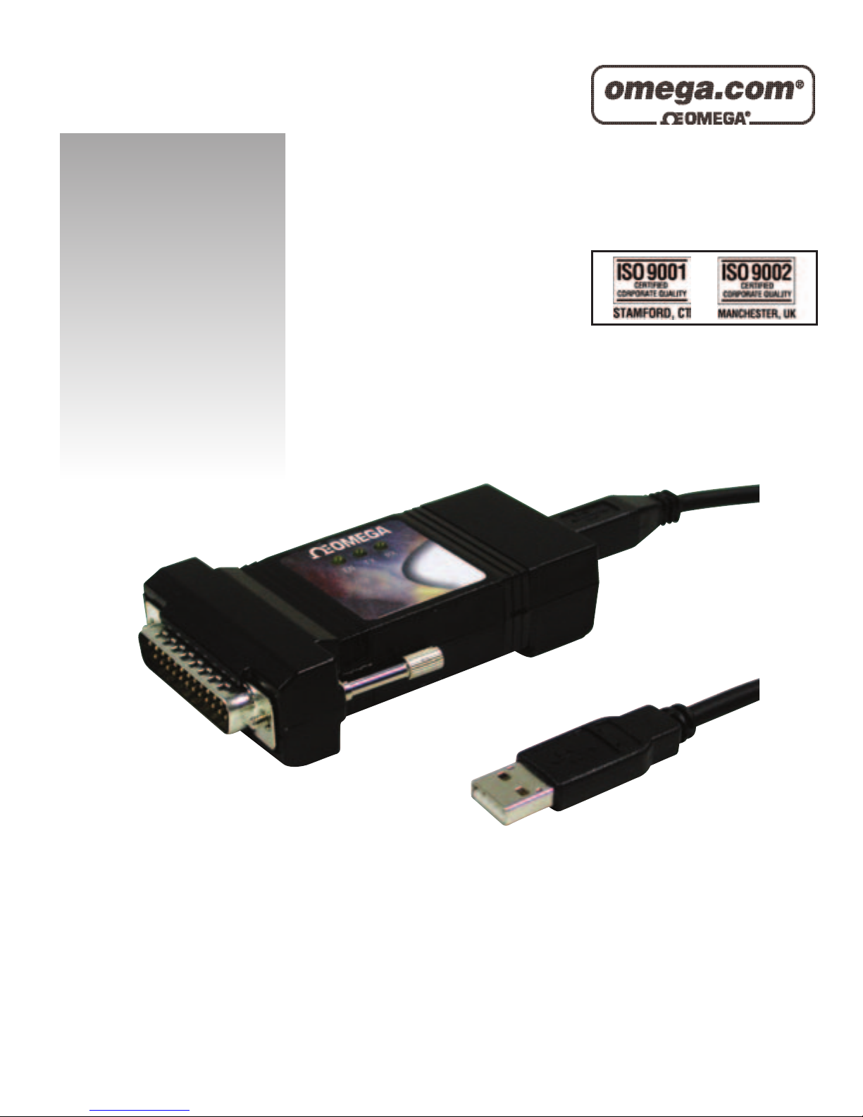
The OMG-USB-485-1equips the PC with 1 USB to RS-530/422/485
Asynchronous serial port providing a versatile interface for common RS-
530/422/485 needs. The advantage of this product over more traditional
approaches is that it doesn’t require opening the computer case, nor does it
require resources such as I/O ports or IRQ’s. It does require a system that
supports USB both in terms of hardware and operating system.
What’s Included
The OMG-USB-485-1 is shipped with the following items. If any of these items
is missing or damaged, contact the supplier.
•OMG-USB-485-1 USB to RS-530/422/485 Serial I/O Adapter
•USB Cable Part Number CA179 for Connecting to Upstream
Host/Hub
•Software

Installation
OMG-USB-485-1Page 2
Installation
Operating System Installation
Choose Install Software at the beginning of the CD and select the Serial I/O
software drivers and install SeaCOM.
System Installation
The screen captures below are taken from a Windows 98 installation. Your
particular operating system may differ slightly from what is shown based on your
version of windows.
The OMG-USB-485-1: can be connected to any Upstream Type “A” port either
at the PC host or an Upstream Hub. The OMG-USB-485-1 is hot-pluggable,
meaning there is no need to power down your computer prior to installation. The
OMG-USB-485-1: requires no user hardware configuration since there are no
jumpers present on the card.
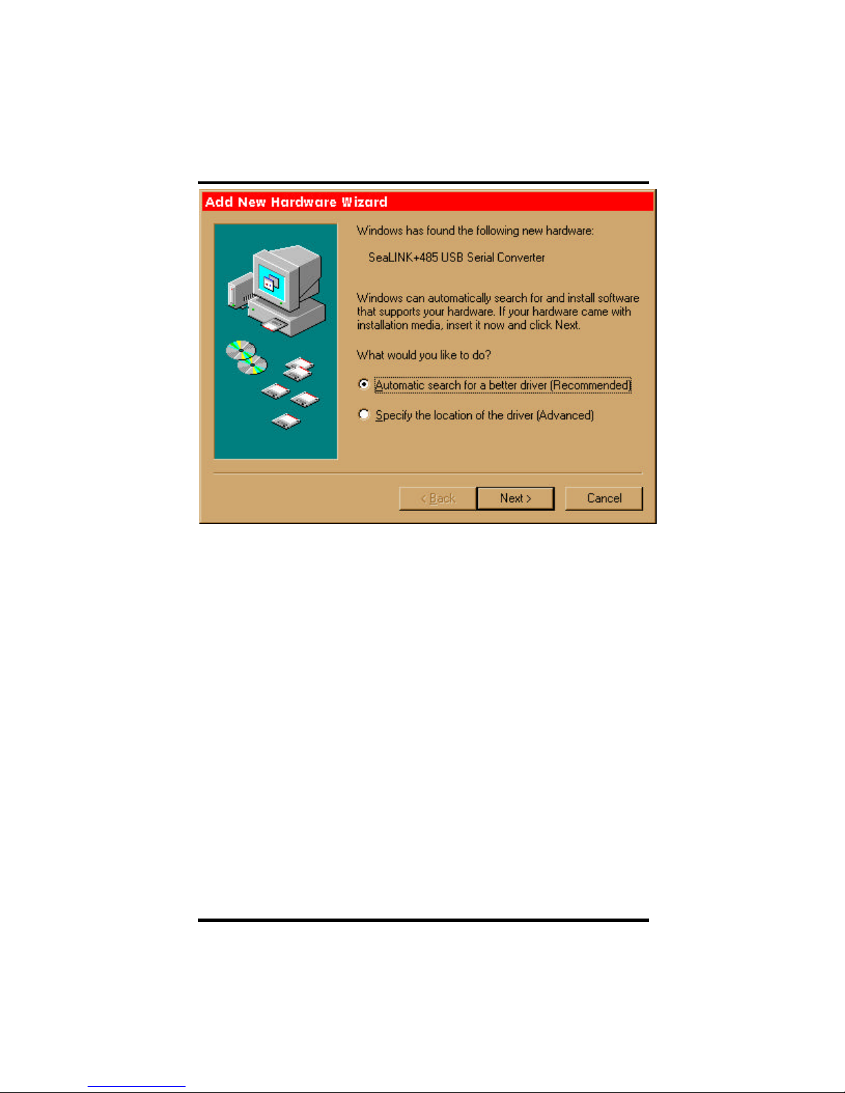
1. Connect OMG-USB-485-1to an Upstream Host or Hub.
This indicates that the system has recognized the new device and will now
proceed to locate a driver.
Installation
OMG-USB-485-1Page 3
Since you have already installed the software by running “Setup”, simply click
“Next” to proceed. The drivers that were installed during setup will automatically
be used to configure the adapter for use.
Installation
OMG-USB-485-1Page 4
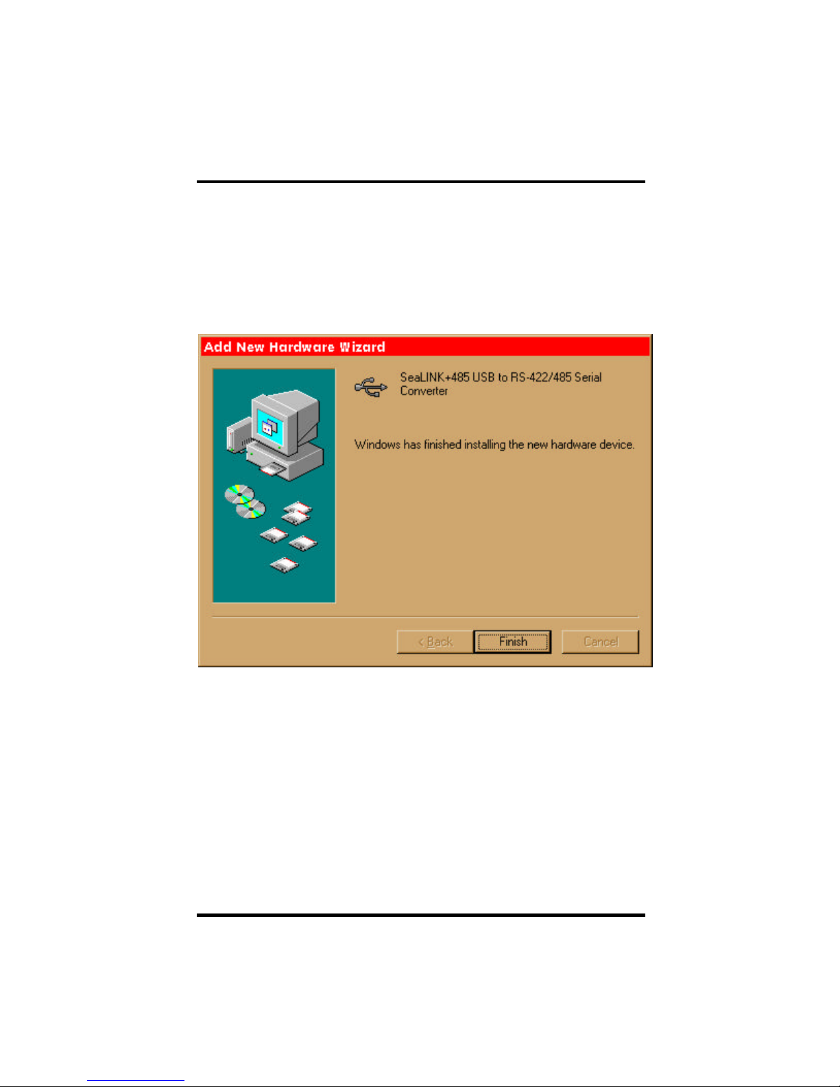
Windows has now located a driver and installed the software. After the driver
has been located click “Finish. You should see one more “New Hardware
Found”, indicating the actual port being created. If you view your systems
Device Manager at this point, you should have a new “COM” port in the
Port(COM & LPT) Device Class. It should look similar to the screen shot on the
following page.
Installation
OMG-USB-485-1Page 5
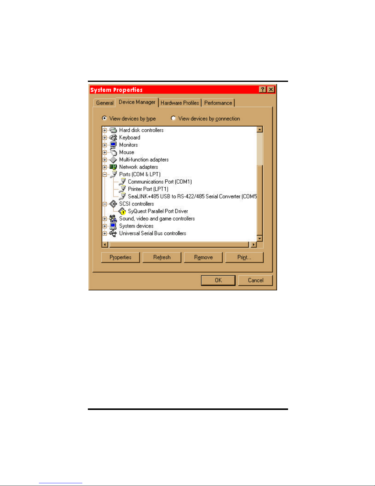
You can access your new COM: port by using the assigned COM: identifier
shown above. In this case, it is COM5: but this assignment will vary from system
to system. At this point, the hardware is recognized. To verify operation use the
supplied WinSSD diagnostic utility. WinSSD can be found in the Start,
Programs group.

Configuration
OMG-USB-485-1Page 6
Configuration
Electrical Interface Selection
The port on the OMG-USB-485-1 has the ability to be used as RS-530/422/485,
RS-422 or 2 wire RS-485. This is selectable via the DIP-switch SW1. The chart
below describes each of the switch position’s function. Please refer to the
following page for switch setting examples. Switch SW1 ON enables, adds and
connects. SW1 position OFF disables, removes and disconnects.
SW1 Function
1RS-485 Two Wire Auto Enable/Disable
2Echo Enable/Disable
3Adds or removes the 120 ohm termination
4Adds or removes the 1K ohm pull-up resistor in the RS-422/RS-485
receiver circuit (Receive data only)
5Adds or removes the 1K ohm pull-down resistor in the RS-422/RS-485
receiver circuit (Receive data only)
6Connects the TX+ to RX+ for RS-485 two wire operation
7Connects the TX-to RX-for RS-485 two wire operation
8Not Used
Inhaltsverzeichnis
Andere Omega Adapter Handbücher


