OSS EB4400 5-SLOT Gen4 Bedienungsanleitung

INSTALLATION GUIDE
EB4400 5-SLOT GEN4
EB4400 5-SLOT Gen4
www.onestopsystems.com

One Stop Systems
EB4400 (5-SLOT BP) 2
Table of Contents
1Introduction................................................................................................................................................................... 5
1.1 General Specifications...............................................................................................................................................................................5
1.2 Features ....................................................................................................................................................................................................6
1.3 EB4400 Architecture (5 Slot) ..................................................................................................................................................................... 6
1.4 PCIe Slots .................................................................................................................................................................................................. 6
1.5 Backplane Block Diagram..........................................................................................................................................................................7
1.6 Dimensions................................................................................................................................................................................................8
1.7 Parts Overview.......................................................................................................................................................................................... 9
1.8 HIB x16 Gen 4 Card ................................................................................................................................................................................. 11
1.9 Backplane................................................................................................................................................................................................12
1.10 Slot Configurations ............................................................................................................................................................................13
1.11 Use Case Diagrams ............................................................................................................................................................................14
1.12 Main Components ............................................................................................................................................................................. 15
1.13 Pre-Installation Information ..............................................................................................................................................................15
1.14 Tools Required for Installation........................................................................................................................................................... 15
1.15 Items List ...........................................................................................................................................................................................15
2Getting Started .............................................................................................................................................................16
3Installation Overview ....................................................................................................................................................16
4Hardware Set-up / Installation ......................................................................................................................................17
4.1 Remove Top Cover..................................................................................................................................................................................17
4.2 Install Target Card ...................................................................................................................................................................................17
4.2.1 Target Card Configuration ................................................................................................................................................................. 17
4.3Install Host Card......................................................................................................................................................................................18
4.3.1 Host Card Configuration...............................................................................................................................................................18
4.4 Dip switch Settings.................................................................................................................................................................................. 20
5GPU / PCIe Cards Installation ........................................................................................................................................21
5.1Before you begin ...............................................................................................................................................................................22
5.2 Install GPU or PCIe card ..........................................................................................................................................................................22
5.3 Connect Auxiliary Power Cables............................................................................................................................................................. 23
6Connect Link Cables ......................................................................................................................................................25
6.1 Mini-SAS HD SFF-8644 Cable Installation ................................................................................................................................................25
6.1.1 x16 Configuration: FOUR cables ................................................................................................................................................... 25
6.1.2 x8 Configuration: TWO cables ......................................................................................................................................................26
6.1.3 x4 Configuration: ONE cable......................................................................................................................................................... 27
6.2 Disconnecting Mini-SAS HD SFF-8644 Cable............................................................................................................................................28

One Stop Systems
EB4400 (5-SLOT BP) 3
7Applying Power Correctly..............................................................................................................................................29
7.1 Connecting to electrical outlet................................................................................................................................................................29
7.2 Connect Power Cord(s) ...........................................................................................................................................................................29
8Powering UP the Computer...........................................................................................................................................31
9Hardware Check............................................................................................................................................................32
9.1 Verify Board LEDs.................................................................................................................................................................................... 32
9.2 Fault LEDs (RED)......................................................................................................................................................................................33
9.3 Verify Adapter Card LEDs ........................................................................................................................................................................34
9.4 Adapter Card LED Definitions..................................................................................................................................................................35
9.5 Slot LEDs.................................................................................................................................................................................................. 35
9.6 Power Distribution Board LED.................................................................................................................................................................36
9.7 Front LED................................................................................................................................................................................................. 36
9.8 Power Supply LED Indicator ....................................................................................................................................................................37
10 Software Installation.....................................................................................................................................................38
10.1 Software Driver Installation...............................................................................................................................................................38
11 Verify HIB Device ..........................................................................................................................................................39
11.1 Linux OS............................................................................................................................................................................................. 39
11.2 Windows 10 / Server .........................................................................................................................................................................41
11.2.1 HIB Cards and Backplane..............................................................................................................................................................41
12 Verify PCIe cards ...........................................................................................................................................................43
12.1 Linux ..................................................................................................................................................................................................43
12.2 Windows............................................................................................................................................................................................44
13 IPMI ..............................................................................................................................................................................46
13.1 Connect Ethernet Cables ...................................................................................................................................................................46
13.2 Locate Mac Address & IP Address...................................................................................................................................................... 47
13.3 Start Internet browser .......................................................................................................................................................................48
14 Other Technical Information .........................................................................................................................................49
14.1 Upstream and Downstream Slots ......................................................................................................................................................49
14.2 Slot LEDs ............................................................................................................................................................................................ 49
14.3 Board LEDs.........................................................................................................................................................................................50
14.4 Slot Type............................................................................................................................................................................................ 50
14.5 PS_ON................................................................................................................................................................................................50
14.6 ARF6 Connector.................................................................................................................................................................................51
14.6 Slot Number and Port Mapping......................................................................................................................................................... 51
14.7 Power Cords ......................................................................................................................................................................................52

14.7.1 Specifications ............................................................................................................................................................................... 52
14.7.2 Power cord socket and voltage tables world standards ...............................................................................................................52

One Stop Systems
EB4400 (5-SLOT BP) 4
14.8 Power Supply.....................................................................................................................................................................................53
14.9 Removing AC Power Supply...............................................................................................................................................................54
14.9.1 Specifications ............................................................................................................................................................................... 55
14.9.2 LED Indicator ................................................................................................................................................................................56
14.10 Fan.....................................................................................................................................................................................................57
14.10.1 Fan Specifications ........................................................................................................................................................................... 57
14.10.2 How to remove Fan........................................................................................................................................................................58
14.11 Fan Foam Air Filter...........................................................................................................................................................................58
14.12 Auxiliary power cables.......................................................................................................................................................................59
14.12.1 Aux power cable installation................................................................................................................................................... 60
14.12.2 Pin Outs...................................................................................................................................................................................61
14.12.3 Using the Auxiliary Power Cable ............................................................................................................................................ 63
14.13 Expansion Unit Power Consumption ................................................................................................................................................. 65
14.14 Power consumption breakdown per hardware .................................................................................................................................65
15 Troubleshooting............................................................................................................................................................66
15.1 Device is not detected or recognized.................................................................................................................................................66
15.2 My PCIe devices are showing UP with a Yellow Exclamation mark....................................................................................................66
15.3 No link between host and target cards..............................................................................................................................................66
15.4 Broken OSS-Backplane.......................................................................................................................................................................66
15.5 My PCIe cards are not detected.........................................................................................................................................................66
15.6 Windows Error Codes ........................................................................................................................................................................67
15.7 System board fails to power UP.........................................................................................................................................................67
15.8 PCIe Upstream and Downstream Ports are not detected..................................................................................................................68
15.9 Support for 3rd Party PCIe Cards ........................................................................................................................................................ 68
16 How to Get More Help ..................................................................................................................................................69
16.1 Contacting Technical Support ............................................................................................................................................................69
16.2 Returning Merchandise ..................................................................................................................................................................... 69
16.3 Third Party Hardware & Software Support Policy..............................................................................................................................69
16.4 Online Support Resources ................................................................................................................................................................. 69

One Stop Systems
EB4400 (5-SLOT BP) 5
1 Introduction
This 5-slot expansion platform provides PCIE expansion in a dense, rugged form factor. The EB4400 supports ONE or TWO PCIe 4.0 x16 host
connections to PCIe 4.0 slots from 1m to 2m away from the host server. The system supports 4 dual-width or 7 single-width full-length PCIe
add-in cards (AICs) such as GPU card, NVME flash and industrial I/O. Two PWM Fans providing high-power add-in card cooling up to 350W per
AIC. Two 1600W or 2600W power supplies provide redundant hot-swap system power with either AC or DC input.
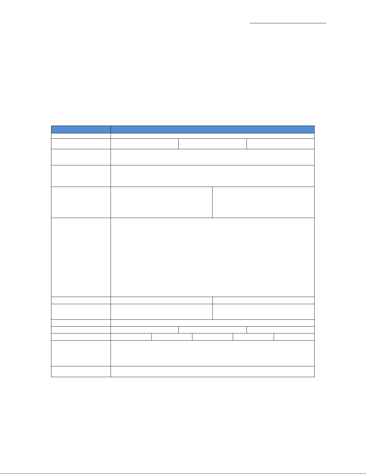
1.1 General Specifications
Item
Description
System
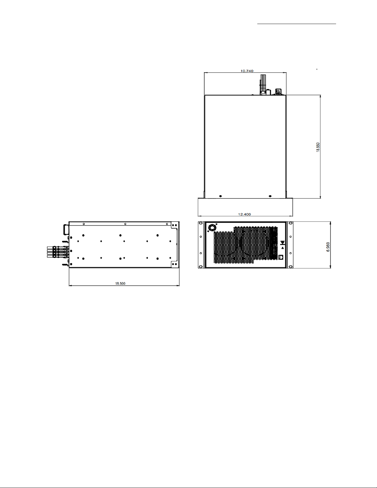
4U Custom Form Factor (10.7” x 7.0” x 18.5”) Net weight 25 lbs.
Host Options
1x PCIe4 x16 Host-to-Target uplink
(32 GB/s)
2x PCIe4 x16 Host-to-Target uplinks
(64 GB/s)
SmartNIC Host
Backplane Options
OSS-538:
1x single-width PCIe 4.0 x16 FHFL upstream slot
4x dual-width PCIe 4.0 x16 FHFL downstream slots
OSS-521:
1x single-width PCIe 4.0 x16 FHFL upstream slot
6x single-width PCIe 4.0 x16 FHFL downstream slots
1x dual-width PCIe 4.0 x16 FHFL downstream slot
Slot Configuration Options
Flex
Modifies one dual-width PCIe 4.0 x16 FHFL
downstream slot to two single-width PCIe
4.0 x16 FHFL downstream slots per
backplane
Riser
Adds an additional single-width PCIe 4.0
FHFL downstream slot per backplane
Environmental Specifications
Temperature:
Operating temp 0 ° to 35 °C ambient.
Short-term (30 mins) operating temp –5°C to 40°C ambient.
Storage temp –40°C to 70°C.
Operational Humidity:
Operating humidity 5-95% (non-condensing)
Storage humidity 0-95% (non-condensing)
Operational altitude:
Operating altitude 6000 ft. at operating temp, 15,000ft. at derated temp. Storage altitude 40,000 ft.
Fans:
3x 180CFM 92mm fans
Default PWM controlled based on built-in temperature sensors
Optional IPMI system monitoring and control
Power Options
Single/Dual AC 1600W
Single/Dual DC 1600W
System Monitoring
Default –automatic dynamic temperature-based fan
speed control
Optional–IPMI system monitoring with power,
temperature, and fan speed control and monitoring
Fan Filters
Optional Quadra foam 45 PPI Replaceable Fan Filters
PCIe 4.0 Cable Lengths
1m
2m
3m
Power Cords
6’ US 110V
6’ US 240V
6’ UK
2’ IEC
6’ IEC
Agency Compliance
Agency Certifications (testing pending):
FCC Class A
CE Safety & Emissions
UL, Cul
RoHS3
Warranty
1 Year Return to Factory. Extended Warranty is available and sold separately.
Upon purchased of a new unit you can buy an extended warranty.

One Stop Systems
EB4400 (5-SLOT BP) 6
1.2 Features
PCIe Gen4 architecture
Small, rugged frame design
Dynamic fan speed control
Configurable slot and host uplinks to optimize throughput
Integrated IPMI based systems monitoring
AC and DC power inlet options
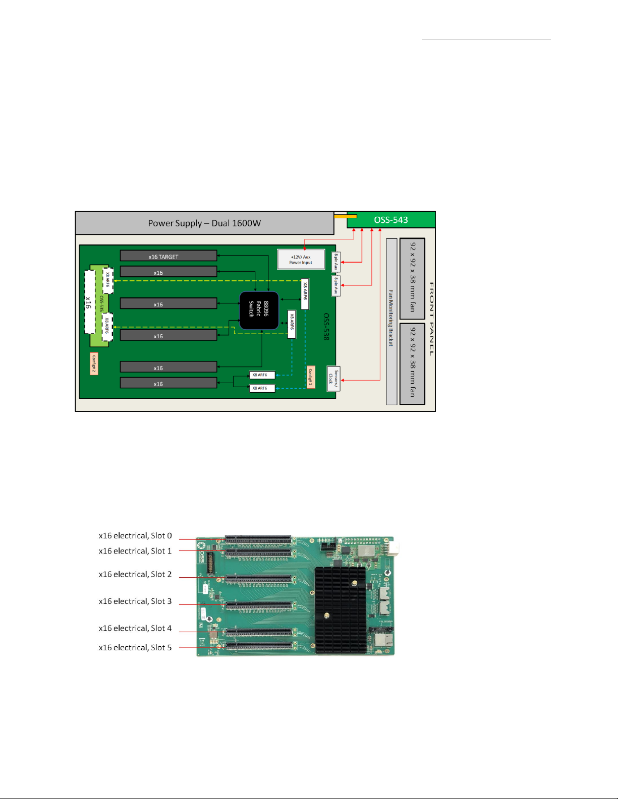
1.3 EB4400 Architecture (5 Slot)
1.4 PCIe Slots
Slot Type: Closed-ended PCIe slot / connector, all the slots are x16 mechanical.
Six x8 electrical slots (slots 1, 2, 3, 4, 5 and 6)
Three x16 electrical slots(slots 0, 7 and 8)

One Stop Systems
EB4400 (5-SLOT BP) 7
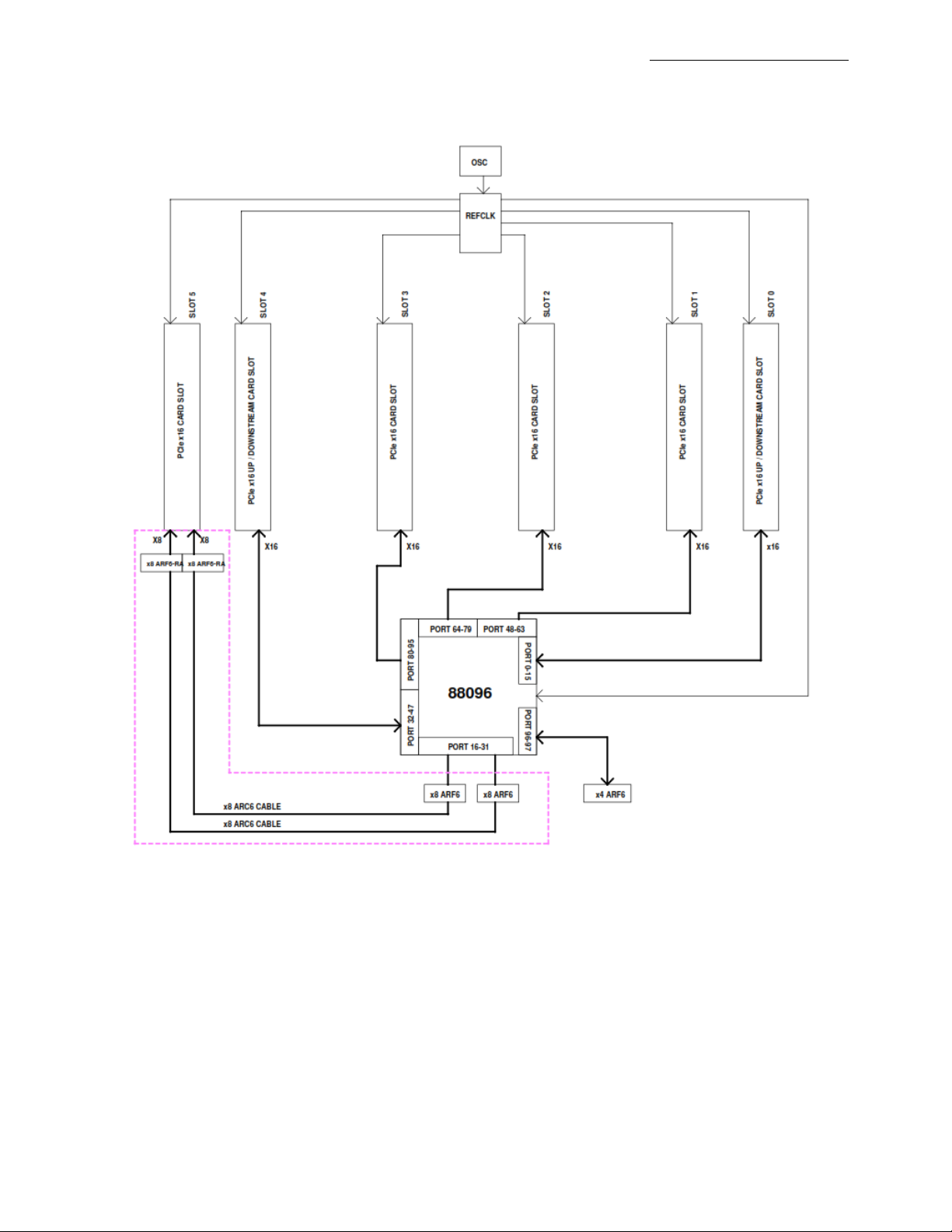
1.5 Backplane Block Diagram

One Stop Systems
EB4400 (5-SLOT BP) 8
1.6 Dimensions

One Stop Systems
EB4400 (5-SLOT BP) 9
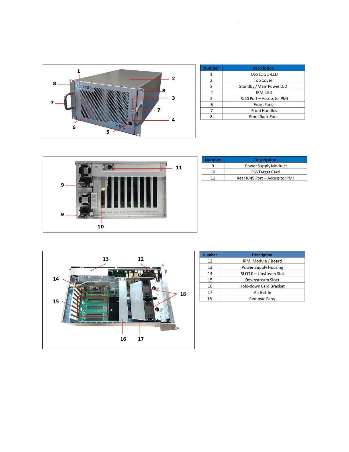
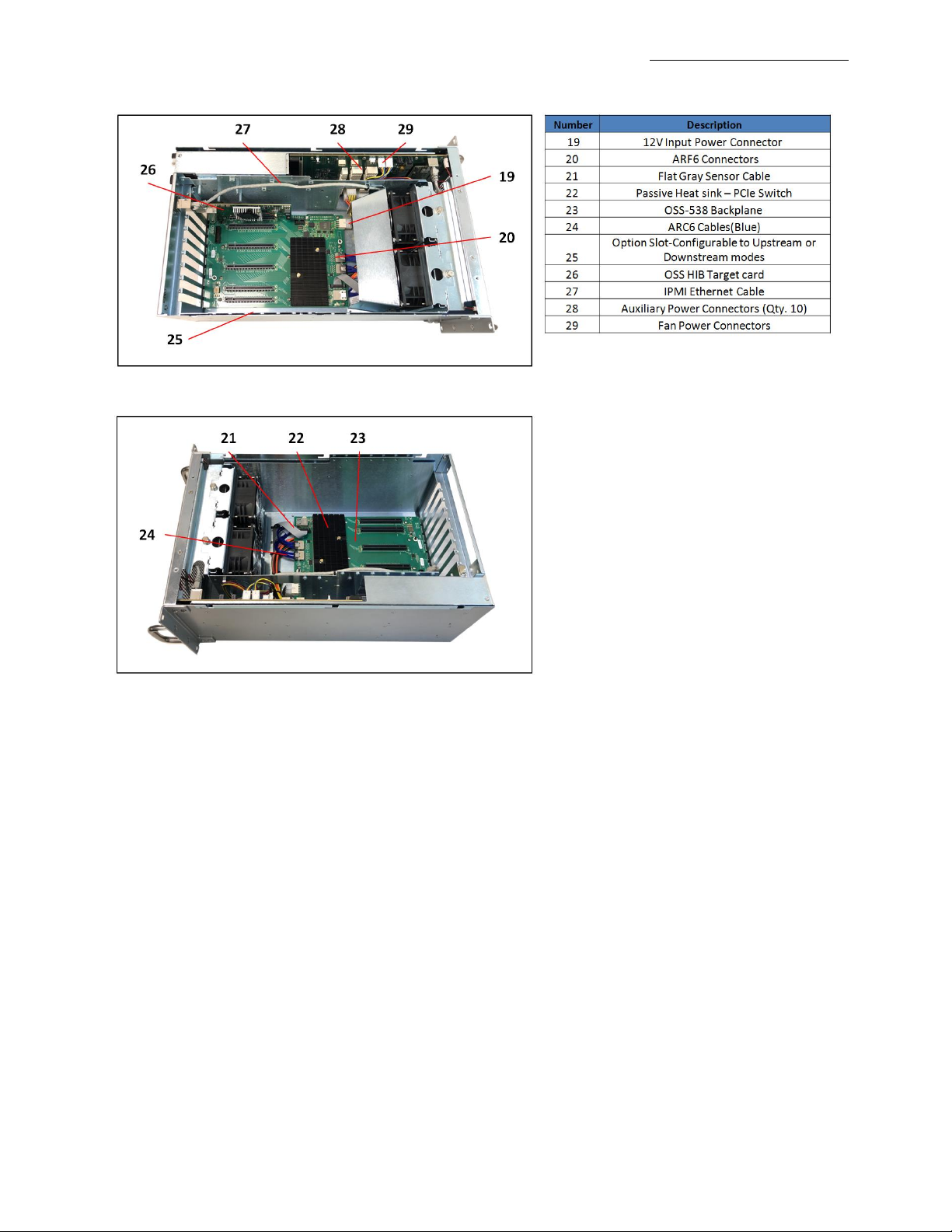
1.7 Parts Overview

One Stop Systems
EB4400 (5-SLOT BP) 10
Inhaltsverzeichnis
Andere OSS Netzwerk-Hardware Handbücher
Beliebte Netzwerk-Hardware Handbücher anderer Marken

Matrix Switch Corporation
Matrix Switch Corporation MSC-HD161DEL Bedienungsanleitung

B&B Electronics
B&B Electronics ZXT9-IO-222R2 Bedienungsanleitung

Yudor
Yudor YDS-16 Bedienungsanleitung

D-Link
D-Link ShareCenter DNS-320L Bedienungsanleitung

Samsung
Samsung ES1642dc Gebrauchsanweisung

Honeywell Home
Honeywell Home LTEM-PV Montageanleitung