Phuel 169-4428-HV0 Bedienungsanleitung

OPS-4428 Rev A
Unit 17 Denmore Industrial Estate, Denmore Road, Bridge of Don, Aberdeen AB23 8JW
User Manual
Tool Catcher
8 ¾’’-4 Quick Union (5’’ Seal Bore)
This Manual Covers the Following Part Numbers:
169-4428-HV0

User Manual
Tool Catcher
OPS-4428 Rev A i
Table of Contents
Revision History ...........................................................................................ii
Safety.............................................................................................................. iii
1Introduction...............................................................................................1
1.1General..............................................................................................1
1.2Product Identification.........................................................................1
2Technical Specification.............................................................................2
2.1General Specifications.......................................................................2
2.1Fishing Neck Limitations....................................................................3
3Technical Description ...............................................................................4
3.1Description.........................................................................................4
3.2Tool String Insertion...........................................................................5
3.3Withdrawal of Tool String (Catching).................................................6
3.4Long Fishing Neck Configuration.......................................................7
4Operation..................................................................................................8
4.1Setting Up..........................................................................................8
4.2Inserting the Tool String.....................................................................8
4.3Operating (Catching) .........................................................................8
4.4Operating (Releasing)........................................................................8
4.5Pre Job..............................................................................................9
4.6During Job.........................................................................................9
4.7Post Job.............................................................................................9
5Maintenance...........................................................................................10
5.1Introduction......................................................................................10
5.2Schedule..........................................................................................10
5.3Safety ..............................................................................................10
5.4Maintenance Record Sheet.............................................................13
6Testing....................................................................................................14
7Parts List and Drawings..........................................................................15
8Spares ....................................................................................................17
Table 1: Technical Data...................................................................................2
Table 2: Maintenance Record........................................................................13
Table 3: Parts List FOR 169-4428-HV0.........................................................15
Table 4: Redress Kit Part No RDK-4428-HV0................................................17
Table 5 : Supporting Equipment.....................................................................17
Figure 1: Tool Catcher Safety......................................................................... iii
Figure 2: Tool Catcher.....................................................................................2
Figure 3: Assembly guide – part 1 .................................................................11
Figure 4: Assembly guide – part 2 .................................................................12
Figure 5: Tool Catcher Assembly...................................................................16


User Manual
Tool Catcher
OPS-4428 Rev A ii
Revision History
Issue, Release Date Description
Rev A, 22 Feb. 12 Initial Issue

User Manual
Tool Catcher
OPS-4428 Rev A iii
Safety
WARNING: Trapped air requires considerable time to compress and
when it is compressed is highly dangerous. It has enough stored
energy to separate parts with considerable force.
Seals in high-pressure vessels are also susceptible to explosive
decompression; the O-rings or rubber gaskets used to seal pressurised
pipelines tend to become saturated with high-pressure gases. If the
pressure inside the vessel is suddenly released, then the gases within
the rubber gasket may expand violently, causing blistering or explosion
of the material.
All pressure equipment has a particular pressure rating and care must be
taken to ensure that no item is used in a situation that may cause its working
pressure to be exceeded.
All personnel involved in pressure testing must be formally trained, competent
and utilising the appropriate PPE.
Safe-Lok devices, where fitted, should be checked for positional security to
avoid unnecessary movement of the collar
Ensure the identification band/plate is fitted and is displaying the correct
information as per the Tag Sheet/Index
This equipment and the equipment it is attached to is heavy never position
yourself below a suspended load
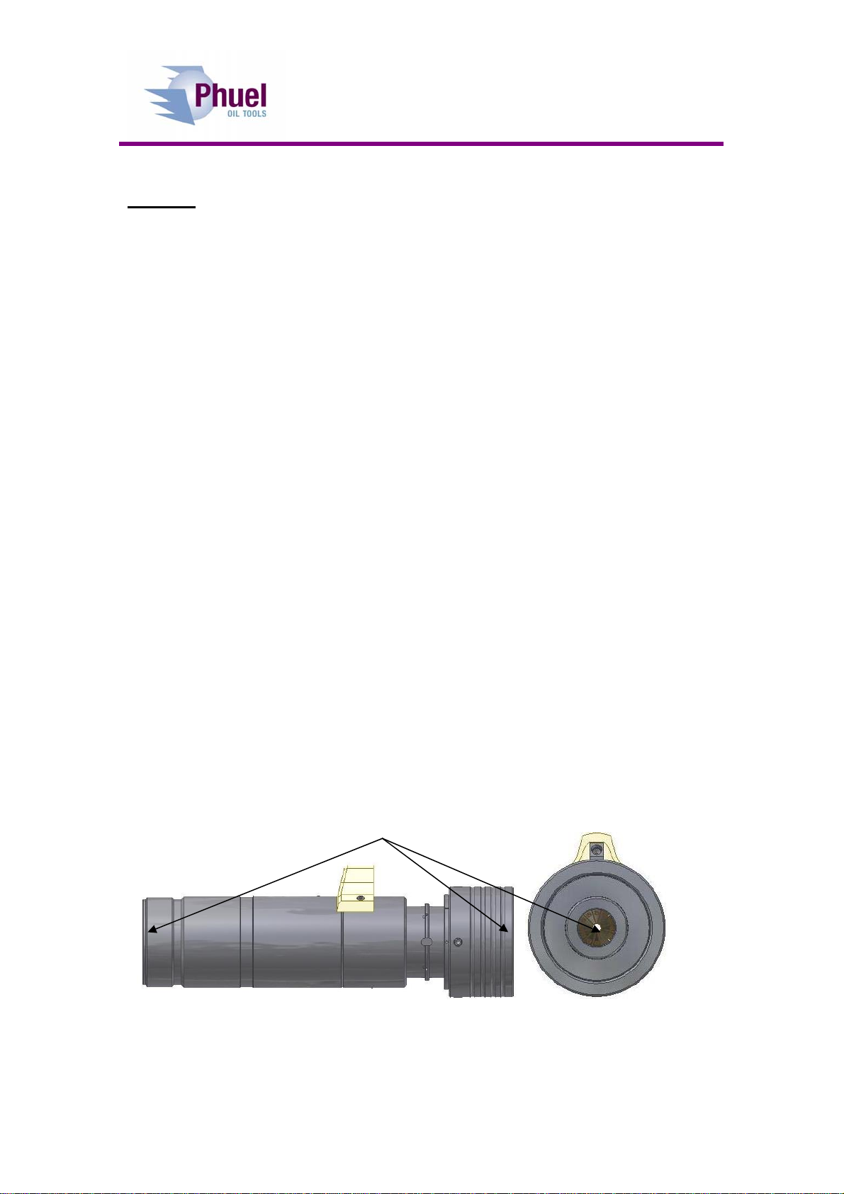
Figure 1: Tool Catcher Safety
Finger, Glove and
Loose clothing trap
areas

User Manual
Tool Catcher
OPS-4428 Rev A 1
1 Introduction
1.1 General
The IRIS tool catcher dispenses with the traditional collet style grapples,
which are restricted in the range of fishing necks that can be caught, and
instead introduces a unique array of shaped fingers that form a spring loaded
iris that automatically adapts to suit any size of fishing neck.
This user manual serves as an introduction to the equipment and contains the
relevant specifications, operation, planning and maintenance instructions,
parts list and drawings.
1.2 Product Identification
Phuel products are identified by a unique serial number that facilitates full
product traceability. Each product is supplied with a documentation pack that
contains product certification and material/inspection reports. The serial
number is always etched on the surface of the product but can sometimes be
difficult to find or read after painting. A customer identification number is also
included to allow the customer to track the asset in their system.
A stainless steel band secures the nameplate tag that is stamped with the
information shown below. This tag should be located in the first instance to
ensure that this manual refers to the correct equipment.

User Manual
Tool Catcher
OPS-4428 Rev A 2
2 Technical Specification
2.1 General Specifications
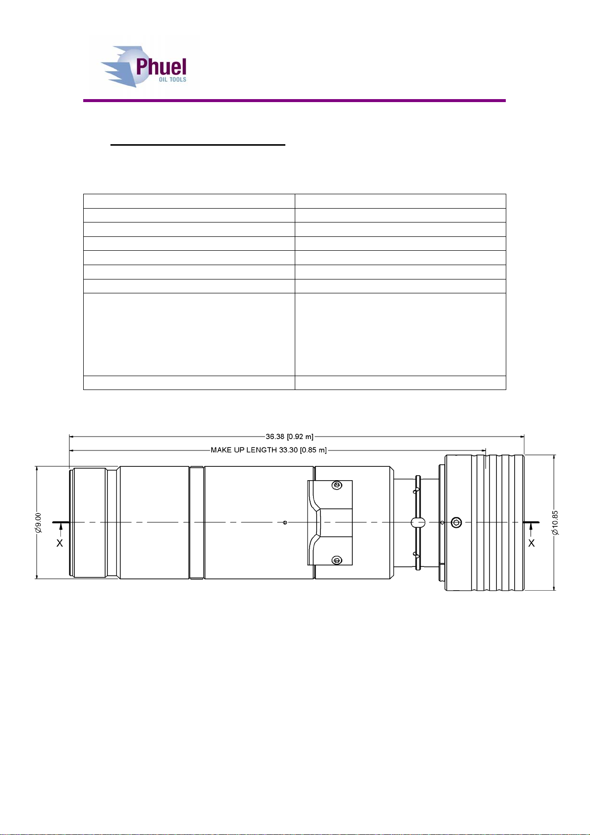
Part Number 169-4428-HV0
Connection 8 ¾-4’’ Acme (5’’ Seal Bore)
Maximum Working Pressure 15,000 Psi
Weight 423 lbs / 192 kg
Overall Length (A) 36.38’’ / 0.92m
Make Up Length (B) 33.30’’ / 0.85m
Hydraulic Connection ½’’ NPT
Maximum Hydraulic Pressure
3,000 psi
Typically only 500 psi is required to
release with no tool string weight
Typically 1,000 psi is required to
release with 1000 Kg of tool string
weight
Fish Neck Sizes See Section 2.1
Table 1: Technical Data
Figure 2: Tool Catcher

User Manual
Tool Catcher
OPS-4428 Rev A 3
2.1 Fishing Neck Limitations
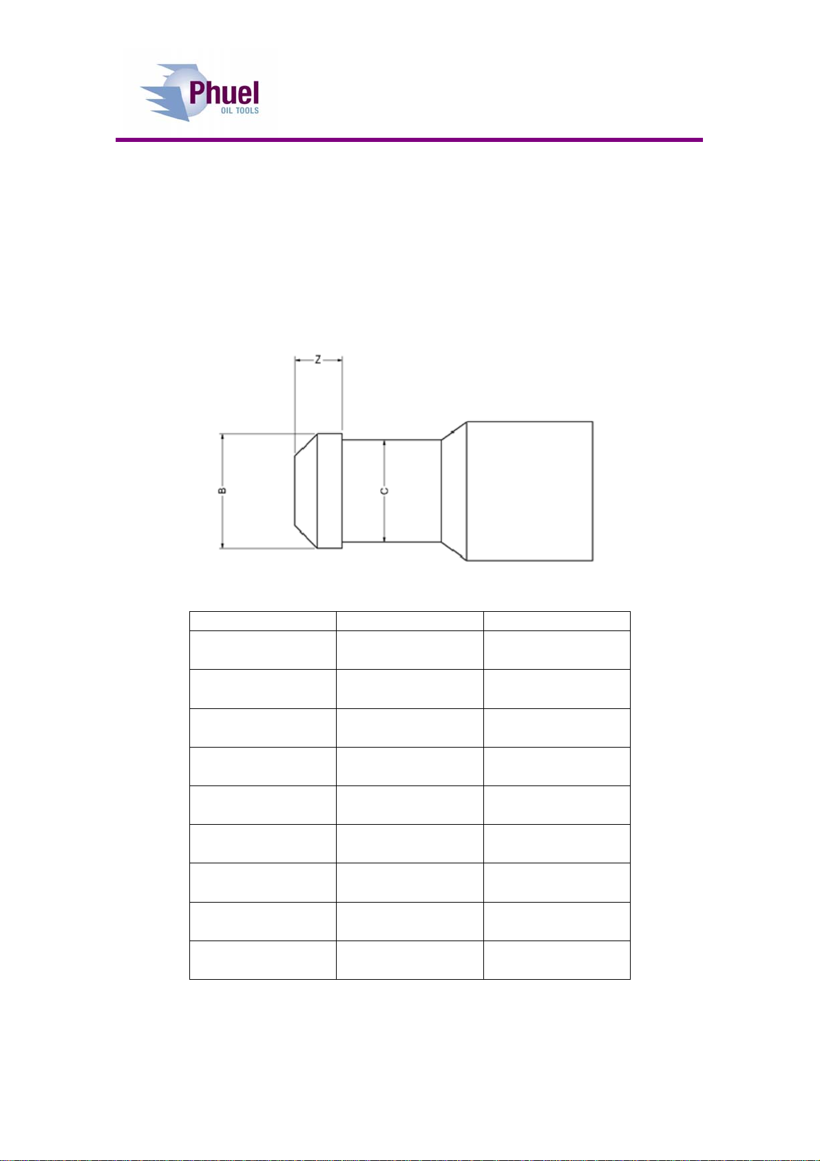
Fishing necks generally conform to an unofficial industry standard, but there
are some products on the market that fail to comply. The fishing neck head
length (Z) should therefore be measured to confirm that it will fit inside the gap
between the two sets of finger rings. If the head length (Z) is larger then it will
be necessary to remove the upper set of fingers and replace it with the Spacer
Ring, bought seperately (see Section 8.1.2)
B C (Ref) Z Max
0.531 in
13.49 mm 0.47 in
11.94 mm 1.744 in
44.30 mm
0.687 in
17.45 mm 0.59 in
14.99 mm 1.667 in
42.34 mm
0.750 in
19.05 mm 0.62 in
15.75 mm 1.637 in
41.58 mm
1.000 in
25.40 mm 0.81 in
20.57 mm 1.529 in
38.84 mm
1.187 in
30.15 mm 1.06 in
26.92 mm 1.456 in
36.98 mm
1.375 in
34.93 mm 1.19 in
30.23 mm 1.388 in
35.26 mm
1.750 in
44.45 mm 1.50 in
38.10 mm 1.270 in
32.26 mm
2.313 in
58.75 mm 2.06 in
52.32 mm 1.125 in
28.58 mm
2.750 in
69.85 mm 2.50 in
63.50 mm 1.040 in
26.42 mm

User Manual
Tool Catcher
OPS-4428 Rev A 4
3 Technical Description
3.1 Description
The IRIS Tool Catcher is designed to prevent tool strings from falling
downhole in the event of a breakage in the wire after the rope socket has
struck the stuffing box. The unique IRIS fingers will catch in the recess of the
fishing neck and lock the tool string in position. The Tool string can be
released by applying hydraulic pressure to the piston to open the fingers –
note that this will occur even with significant tool string weight so operators
must guard against the dropping of the string when hydraulic pressure is
applied.
There are twelve independent fingers mounted on a pivot joint that are spring
closed. The upward movement of the tool string will naturally open the fingers
against the spring, and they will then collapse into the recess below the fishing
neck. When the tool direction is reversed the sharp angle at the base of the
fishing neck prevents the fingers from opening allowing the whole tool string
weight to be supported.
There is a second set of IRIS fingers mounted in the reverse direction and the
top of the tool catcher. This group acts as a stop for the tool string to ensure
that the lower set of fingers is correctly positioned to catch the fishing neck
upset. The upper set is also mounted on a shock absorber so that any upward
momentum is dissipated with minimum shock loading to the wire and the tool
string. The fact that we are using IRIS fingers as an upward stop has the
additional benefit that the tool string can now be loaded through the tool
catcher from the top, which greatly simplifies the set up operation. Note that
the tool string cannot be withdrawn from the top unless the top set of fingers
are being held open with a suitable, locally manufactured, tubular sleeve (not
supplied).
The Tool catcher is moved into the release position by applying hydraulic
pressure to the piston, which will move upwards and force the fingers into the
open position. With the piston fully extended the fingers are open to allow full
bore access to the tool string.
Note: The second set of iris fingers can be removed and replaced with a
spacer ring (supplied) if a longer fish neck is to be used. Care must be taken
that the fingers can only catch in the correct recess when the tool strings
stops and the top of the riser.

User Manual
Tool Catcher
OPS-4428 Rev A 5
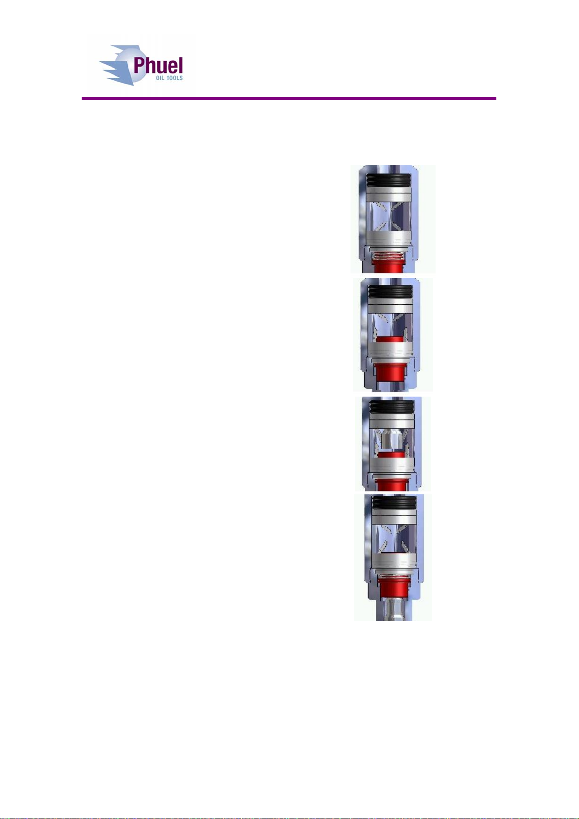
3.2 Tool String Insertion
Ensue tool catcher set up for
correct length of fish neck
Visually check both sets of
fingers are closed
Attach hydraulic hand pump to
½’’ NPT fitting and apply
pressure to open the bottom
set of fingers
Insert tool string allowing it to
pass through both sets of
fingers
Release pressure allowing the
fingers to close
Remove hand pump

User Manual
Tool Catcher
OPS-4428 Rev A 6
3.3 Withdrawal of Tool String (Catching)
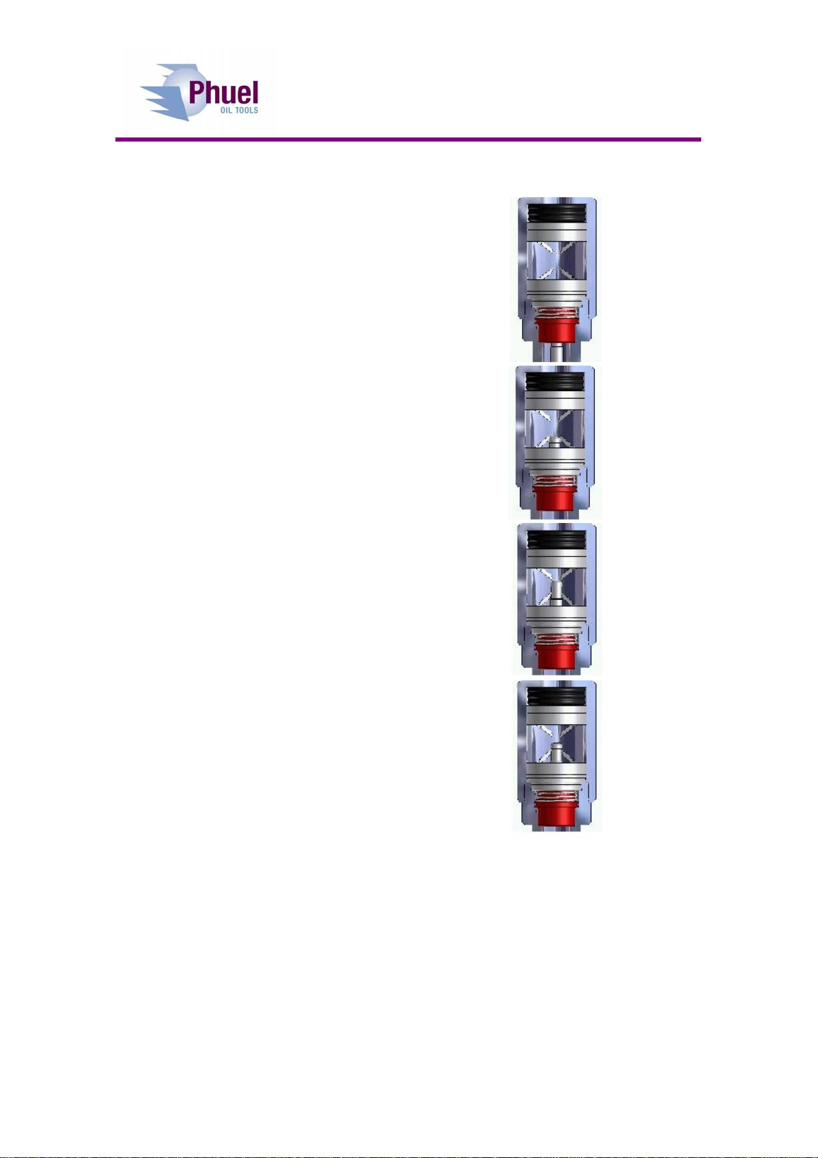
Tool string withdrawn from well
As tool approaches iris fingers they
automatically open allowing tool to
pass
Once wider part of tool passes
through iris the fingers close to the
size of the tool neck
Upper set of fingers act as a buffer to
prevent tool from being totally
withdrawn from the catcher
With tension released on the tool
string the tool drops and rests on the
iris fingers
Note: if a longer fish neck is used the upper set of fingers are not fitted and
therefore the tool can be withdrawn from the top catcher when rigging down.
Inhaltsverzeichnis