
Power-Pole CM2 HPU Bedienungsanleitung

C-MONSTER Control Systems
& Hydraulics
Manual Outline
Section 1 - Electronics & Controllers
Section 2 - Hydraulics
Effective July 1, 2020

2WARRANTY
CENTER
C
E
R
T
I
F
I
E
D

3
WARRANTY
CENTER
C
E
R
T
I
F
I
E
D
Table of Contents
Section 1: Electronics & Controllers
1.1 HPU Indicator Light Guide .....................................4
1.2 Power Draw of Hydraulic Pumps .................................5
1.3 CM1 Motor Cover Installation ..................................6
1.4 CM2 Motor Cover Installation...................................8
1.5 CM1 Circuit Board Installation ..................................8
1.6 CM2 Circuit Board Installation ..................................9
1.7 CM1 Motor Installation ......................................11
1.8 CM2 Motor Installation ......................................12
1.9 C-Monster Programming & Operation (CM1 & CM2) ............. 14-23
• Top Side Controls ........................................14
• Advanced Surface Mount Remote Control ......................16
• Remote Control Key Fob ...................................18
• Wireless Foot Switches.....................................19
• Advanced Foot Switch (CM1) ................................20
• Advanced Key Fob (CM1) ..................................22
1.10 C-Monster Controller Battery Replacement (CM1 & CM2) ............24
SECTION 1 – Electronics & Controllers
Section 1:
Electronics & Controllers

4WARRANTY
CENTER
C
E
R
T
I
F
I
E
D
SECTION 1.1 – Electronics & Controllers
LED
PROGRAM button
C-Monster 1.0: Indicator Light Guide
LIGHT INDICATION
Flashing GREEN Light
NORMAL: System has proper voltage (11.3V – 16.4V).
Flashing ORANGE Light LOW: System has low voltage (10.3V – 11.2V).
Flashing RED Light WARNING: System has low voltage (10.2V or less).
NOTE: When voltage is below 8.2V or above 16.5V
the unit will not operate.
C-Monster 2.0: Indicator Light Guide
LIGHT INDICATION
Flashing GREEN Light NORMAL: System has proper voltage (11.9V – 16.4V).
Flashing ORANGE Light LOW: System has low voltage (10.8V – 11.8V).
Flashing RED Light WARNING: System has low voltage (10.7V or less).
NOTE: When voltage is below 6V or above 16.5V
the unit will not operate.
LED
DOWN button
PROGRAM button
UP button
HPU (Hydraulic Pump Unit) Indicator Light Guide

5
WARRANTY
CENTER
C
E
R
T
I
F
I
E
D
SECTION 1.2 – Electronics & Controllers
Power Draw of Hydraulic Pumps
CM1 & CM2 Units
GLOSSARY:
Amps (A): The amount of current that is flowing through the circuit at a given time
MilliAmps (mA): One thousandth of an amp, a measure for small electric currents
Hibernation: Low-Power mode HPU enters into when not used for a set period of time
NOTES:
• Current firmware for CM2 pumps set to “Never” hibernate
• Current firmware for CM1 pumps set to hibernate after 6 hours
• Hibernation settings can be changed via the C-Monster App
Startup: Initial draw of power when HPU first turns on. Amperage draw will drop after a period of time
Operation: Draw of power when HPU is running (raising or lowering anchor). Amperage draw will vary
slightly among anchor models Other variables may also effect amperage draw during operation.
Standby: HPU is on and ready to use (anchor is in stowed or anchored state)
CM2 HPU
MODE POWER DRAW LED STATUS
Hibernation ≈6 mA Not Blinking
Startup ≈80 mA (for 2 minutes) Blinking
Operation Blade ≈25 A to ≈35 A Max
Pro/SPN ≈15 A to ≈28 A Max
Blinking
Standby ≈21 mA Blinking
CM1 HPU
MODE POWER DRAW LED STATUS
Hibernation ≈40 mA Not Blinking
Startup ≈2 A (less than 5 seconds) Blinking
Operation Blade ≈25 A to ≈35 A Max
Pro/SPN ≈15 A to ≈28 A Max
Blinking
Standby ≈80 mA Blinking

6WARRANTY
CENTER
C
E
R
T
I
F
I
E
D
Figure 1
Figure 2
Membrane Switch
Ribbon Wire
SECTION 1.3 – Electronics & Controllers
C-Monster 1.0 Motor Cover Installation
REMOVAL:
STEP 1 Disconnect the RED 12V (+) wire from the battery source, or remove the inline fuse.
STEP 2 Remove the four Phillips Head Bolts that hold the cover on the C-Monster Motor Assembly.
FIG 1
STEP 3 With the cover removed, disconnect the Membrane Switch Ribbon Wire from the Circuit Board by
gently pulling on it. FIG 2
INSTALLATION:
STEP 1 Follow REMOVAL STEPS 2 & 3 in reverse order.
STEP 2 Re-install the cover with the four Phillips Head Bolts.
STEP 3 Re-connect the RED 12V (+) wire to the battery source, or re-install the inline fuse.

7
WARRANTY
CENTER
C
E
R
T
I
F
I
E
D
Figure 1
Figure 3
Power Cord
Motor Cover
Circuit board
Pump casing groove made
for circuit board.
Figure 2
Rubber Membrane
CLICK
Motor Cover
Motor Cover Tab
SECTION 1.4 – Electronics & Controllers
C-Monster 2.0 Motor Cover Installation
REMOVAL:
STEP 1 Pull on the Motor Cover Tab to release Pump Cap. FIG 1
INSTALLATION:
STEP 1 With the Rubber Membrane, Power Cord and Circuit Board fully seated into the Pump
Casing Groove, re-install the Motor Cover. FIG 2 & 3

8WARRANTY
CENTER
C
E
R
T
I
F
I
E
D
SECTION 1.5 – Electronics & Controllers
C-Monster 1.0 Circuit Board Installation
REMOVAL:
STEP 1 Disconnect the RED 12V (+) wire from the Battery Source or remove the Inline Fuse.
STEP 2 Remove the Motor Cover by unscrewing the four Phillips Head Bolts that attach the Cover to the Motor
Assembly. FIG 1
STEP 3 Gently pull the Membrane Switch Ribbon Wire to disconnect it from the Circuit Board. FIG 2
STEP 4 Disconnect the RED 12V (+) and BLACK 12V (-) wires from the Circuit Board.
STEP 5 Grab the sides of the Circuit Board and carefully slide it upward out of the Motor Assembly. FIG 3
STEP 6 Disconnect the three Brushless Motor Wires.
NOTE: The Brushless Motor Wires are labeled “U”, “V”, and “W.” These letters correspond to labels on the
Circuit Board. FIG 3
INSTALLATION:
STEP 1 Follow REMOVAL STEPS 3-6 in reverse order to reconnect wiring.
IMPORTANT! Ensure that the Brushless Motor Wires and the 12V Wires are connected to the proper terminals
on the new Circuit Board.
STEP 3 Route the white Antenna Wire as shown in FIG 4.
WARNING! Improper wiring will result in signal interference.
STEP 5 Reinstall the Cover with the four Phillips Head Bolts.
STEP 6 Reconnect the RED 12V (+) wire to the Battery Source, or re-install the Inline Fuse.
STEP 7 Program the new Circuit Board. Section 1.9 C-Monster Top Side Controls
Figure 1
Figure 3
Figure 2
Figure 4
Negative and positive terminals
Brushless Motor Wires
Antenna Wire
Membrane Switch
Ribbon Wire

9
WARRANTY
CENTER
C
E
R
T
I
F
I
E
D
SECTION 1.6 – Electronics & Controllers
Figure 1
Figure 2
Circuit board fully seated
and flush with motor
casing at all four corners
Motor casing groove for
circuit board membrane
Circuit board membrane
Pump Cap Tab
Desi-Pak
Figure 2-a
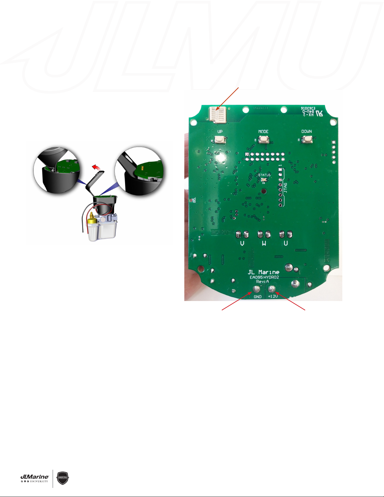
C-Monster 2.0 Circuit Board Installation
REMOVAL:
STEP 1 Disconnect the RED 12V (+) wire from the battery source, or remove the 40 Amp inline fuse.
STEP 2 Remove the Pump Cap by pulling on the Tab and lifting up on the Cap. FIG 1
STEP 3 Remove the Circuit Board Membrane. FIG 2
STEP 4 Pry the front of the Circuit Board up using the Pump Cap and remove it. FIG 3 (next pg.)
IMPORTANT! Be careful not to touch the Antenna as this could damage it. FIG 4 (next pg.)
INSTALLATION:
STEP 1 Install the Circuit Board into the Motor Assembly so that it is flush with the top of Motor Assembly.
FIG 2
IMPORTANT! Make sure the DESI PAK is on the top of motor assembly before installing the new Circuit Board.
FIG 2-a
STEP 2 Install the Circuit Board Membrane so the edge is seated completely in Motor Casing Groove.
FIG 2
STEP 3 Make sure the Power Cord is fully plugged into the Pump and reinstall the Pump Cap.
STEP 4 Reconnect the RED 12V (+) wire to the battery source and make sure the 40 Amp inline fuse is installed.
NOTE: If the buttons stick and cause the Power-Pole to auto run remove the cap and reinstall circuit board
membrane.
10 WARRANTY
CENTER
C
E
R
T
I
F
I
E
D
SECTION 1.6 – Electronics & Controllers
C-Monster 2.0 Circuit Board Installation (continued)
Figure 3
Figure 4
Circuit board antenna (DO NOT TOUCH)
- Ground terminal + Positive terminal
INSTALLATION (Continued):
STEP 5 New circuit boards must be programmed. See Section 1.9: C-Monster Top Side Controls for
programming procedure.
Dieses Handbuch passt für folgende Modelle
1
Inhaltsverzeichnis
Beliebte Wasserpumpe Handbücher anderer Marken


Sykes AmeriPumps
Sykes AmeriPumps GP100M Fehlerbehebungshandbuch

DUROMAX
DUROMAX XP WX Series Bedienungsanleitung

BRINKMANN PUMPS
BRINKMANN PUMPS SBF550 Bedienungsanleitung

Franklin Electric
Franklin Electric IPS Bedienungsanleitung

Xylem
Xylem e-1532 Series Bedienungsanleitung

Milton Roy
Milton Roy PRIMEROYAL Bedienungsanleitung