Resol Solar Manager Pro to LAN Bedienungsanleitung

FB052 Kundenfreigabe:Anleitungen
Customer approval: Manuals
Ident.-Bezeichnung Ident. designation
Anleitung
Manual
Herausgabeindex:
Issue index:
erteilt am:
Date of approval:
Änderungsindex:
Change index:
Art.-Nr.:
Art. no.:
Unterschrift:
Signature:
ja /yes nein /no
Name in Druckbuchstaben:
Name in block letters:
Kundenfreigabe Customer approval
Format:
Format:
RESOL-Basis-Art.-Nr.:
Basic RESOL art. no.:
Datum:
Date:
Bearbeiter:
Issuer:
Bemerkungen:
Remarks:
Urheberrecht / Copyright
Das Copyright für die von der Firma RESOL –Elektronische Regelungen GmbH selbst erstellten Objekte, Dokumente, Grafiken,Abbildungen, Tondokumente,
Videosequenzen,Texte etc. bleibt allein bei der Firma RESOL. Eine Vervielfältigung, Weitergabe an Dritte, Veränderung der Inhalte oder die Verwendung in
elektronischen oder gedruckten Publikationen ist ohne ausdrückliche Zustimmung der Firma RESOL nicht gestattet.
Please note that RESOL – Elektronische Regelungen GmbH owns the sole copyright on objects, documents, graphics, pictures, audio and video documents, texts,
etc. published and created by RESOL – Elektronische Regelungen GmbH. Copying, distribution to third parties, changing the contents or using these contents in
electronic or printed publications is not permitted without the explicit approval by RESOL.
Ariston LAN
11206565
05.09.2014
A6Q
20140411
1.1
K. Erhardt

*11206565*
11206565
Solar Manager Pro
to LAN
Interface adapter
Mounting
Connection
Installation
Adaptateur interface
Montage
Raccordement
Commande
Adaptador de interfaz
Montaje
Conexionado eléctrico
Instalación
Adattatore di interfaccia
Montaggio
Collegamento
Installazione
Manuel
fr
Manual
en
Manual
es
Manuale
it

en
2
Safety advice
Please pay attention to the following safety advice in order
to avoid danger and damage to people and property.
Description of symbols
ATTENTION! Warnings are indicated with a warning tri-
angle!
ÎThey contain information on how to
avoid the danger described.
Signal words describe the danger that may occur, when it
is not avoided.
• ATTENTION means that damage to the appliance can
occur.
• WARNING means that injury, possibly life-threatening
injury, can occur.
ÎArrows indicate instruction steps that should be car-
ried out.
Note
Notes are indicated with an information symbol.
Table of contents
1 Technical data................................................18
2 Mounting........................................................18
3 Electrical connection....................................19
4 Network settings ..........................................21
5 LED at the front of the housing...................26
6 Glossary .........................................................27
Thank you for buying this product.
Please read this manual carefully to get the best perfor-
mance from this unit.
Subject to change. Errors excepted.
© 20140905_11206565_VBus_LAN.mon4s.indd

en
3
Target group
These instructions are exclusively addressed to authorised
skilled personnel.
Only qualied electricians should carry out electrical
works. Initial installation must be effected by the system
owner or qualied personnel named by the system owner.
Instructions
Attention must be paid to the valid local standards, regula-
tions and directives!
Information about the product
Proper usage
The
Solar Manager Pro to LAN
interface adapter may only
be used for connecting an electronic controller for solar
thermal systems to a computer network or PC via the
VBus® in compliance with the technical data specied in
these instructions.Improper use excludes all liability claims.
CE-Declaration of conformity
The product complies with the relevant directives
and is therefore labelled with the CE mark. The
Declaration of Conformity is available upon re-
quest, please contact the manufacturer.
Disposal
• Dispose of the packaging in an environmentally sound
manner.
• Dispose of old appliances in an environmentally sound
manner. Upon request we will take back your old appli-
ances bought from us and guarantee an environmentally
sound disposal of the devices.
Overview
• The network connection for your controller
• Access to the system via the complete network
• Remote parameterisation of the controller viaVBus®
• Full version of the RSC software included on CD-ROM
The
Solar Manager Pro to LAN
interface adapter is de-
signed for the connecting the controller directly to a PC or
router. It enables easy access to the controller via the local
network of the owner.
Thus, controller access, system parameterisation and data
charting can be effected from every workstation of the
network.
The
Solar Manager Pro to LAN
interface adapter is de-
signed for the connection to controllers equipped with a
VBus®.

en
4
1 Technical data
Housing: plastic
Protection type: IP 20 (EN 60529)
Ambient temperature: 0…40 °C
Dimensions: 95 × 70 × 25 mm
Mounting: wall mounting is possible (optional)
Display:
1 bi-coloured LED at the front of the housing
2 LEDs at the RJ45 LAN connection
Power supply:
mains adapter power supply: 100…240V~ /50-60 Hz
interface adapter power supply:12V�/ 0,5A 5.5 × 2.5 mm
Data interface:VBus®, LAN interface
Solar Manager Pro to LAN
Input: 12V / 0,5 A
5.5 x 2.5 mm -+
2 Mounting
The unit must only be located in dry interior rooms. It
is not suitable for installation in hazardous locations.The
interface adapter is light and small enough to not require
any form of mounting.It can be placed directly on the desk
or on a system component (pay attention to the allowed
ambient temperature!).
4 self-adhesive, skid-proof rubber pads are included with
the adapter. If necessary, these can be afxed to the corre-
sponding molds on the base part of the housing to ensure
a secure placement of the device without wall mounting.
If desired, the interface adapter can be mounted to a wall:
ÎMark the desired hanging position on the wall.
ÎDrill and prepare the hole with a wall plug and screw.
ÎHang the device onto the screw.
ÎMark the position for the mounting screw (centres
70 mm).
ÎDrill and prepare the hole with a wall plug.
ÎHang the device and fasten it by means of the second
screw.

en
5
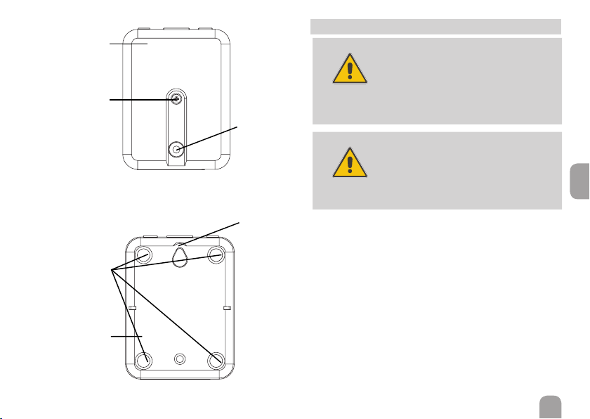
Front view
Back view
Cover screw
Upper part of
the housing
Opening for
the mounting
screw
Molds for the
rubber pads
Hanging
Base part of
the housing
3 Electrical connection
ATTENTION!
ESD damage!
Electrostatic discharge can lead to damage
to electronic components!
ÎTake care to discharge properly be-
fore touching the inside of the device!
To do so, touch a grounded surface
such as a radiator or tap!
ATTENTION!
Short circuit!
A short circuit can lead to damage to elec-
tronic components!
ÎFinish terminal connection and close
the housing before establishing the
mains connection!
The Solar Manager Pro to LAN interface adapter needs a
mains, aVBus®and a LAN connection to function.To install
theVBus®cable, the housing has to be opened.
ÎTo open the housing, unscrew the cover screw and
pull off the upper part of the housing.
ÎConnect the includedVBus®cable to theVBus®termi-
nals with either polarity.
The VBus®cable can be extended or replaced with a two-
wire cable (bell wire).The cross section of the cable must
be at least 0.5mm2and the cable can be extended up to
50m in the case that one module is used.

en
6
ATTENTION!
Low voltage cables must not run together
in a cable conduit with cables carrying a
higher voltage than 50V.
ÎAlways route high and low voltage
cables separately!
ÎPay attention to the local regulations!
ÎClose the housing.
ÎTo close the housing again, relocate the upper part of
the housing and refasten the cover screw.
ÎEstablish the network connection by means of the in-
cluded LAN cable.
ÎEstablish the mains connection by means of the inclu-
ded mains adapter.
The Solar Manager Pro to LAN interface adapter is now
ready for normal operation.
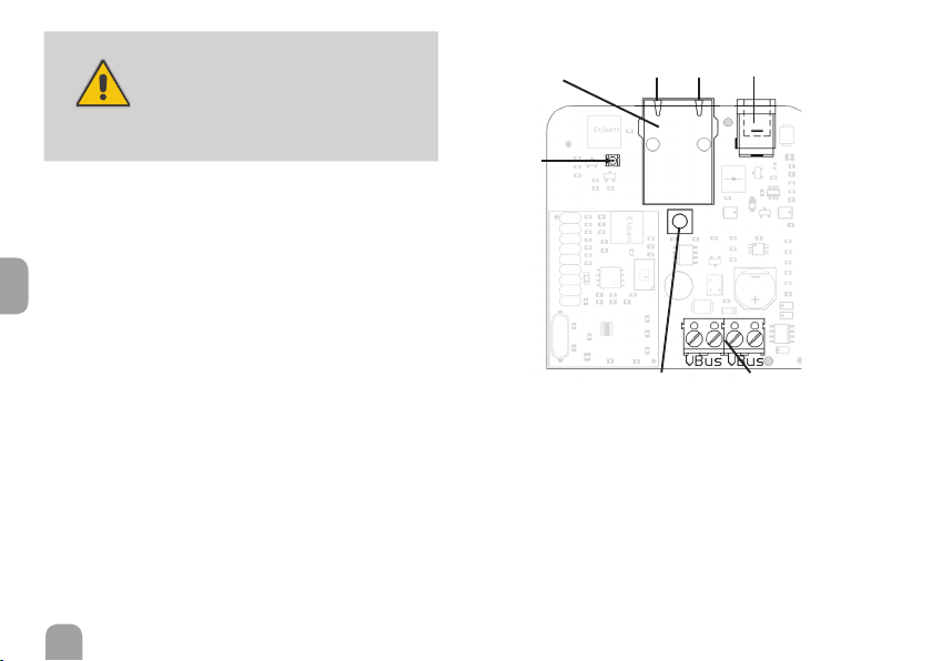
Interior view of the Solar Manager Pro to LAN adapter
RJ45 LAN connector Mains connectorStatus-LEDs
Reset button
Bi-coloured
front-LED
VBus®terminals

en
7
4 Network settings
When UPnP access is activated, the operating system will
automatically recognise the Solar Manager Pro to LAN
interface adapter. Its IP address can then be seen in the
control panel.
Note
In MS Windows from version 7 on, UPnP access is
activated by default. In earlier versions, UPnP access
must be activated manually.
If the IP addresses in the local network are not assigned by
a DHCP server, proceed as follows:
ÎConnect the Solar Manager Pro to LAN interface
adapter directly to a PC.
The network settings of the PC used must be set to DHCP!
ÎCongure the Solar Manager Pro to LAN interface
adapter.
Finding the Solar Manager Pro to LAN interface
adapter in the local network
If the
Solar Manager Pro to LAN
interface adapter is not
recognised automatically, the DeviceDiscoveryTool soft-
ware on the CD-ROM enclosed can be used. In order to
use DeviceDiscovery, Java must be installed.
Web interface
All adjustments for the
Solar Manager Pro to LAN
interface
adapter can be made with the Web interface.
The Web interface is integrated in the
Solar Manager Pro
to LAN
interface adapter and can be run in an Internet
browser.
The Web interface has the following functions:
• Displaying the status of the Solar Manager Pro to LAN
interface adapter.
• Conguring the
Solar Manager Pro to LAN
interface
adapter.
• Adjusting the network settings of the
Solar Manager Pro
to LAN
interface adapter.
In order to access the Web interface, enter the IP address
of the
Solar Manager Pro to LAN
interface adapter into the
address bar of the browser.
The Web interface is not designed for controller access,
but for adjusting the network settings of the
Solar Manager
Pro to LAN
interface adapter.
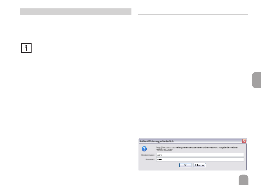
When the Settings menu is selected, an authentication
enquiry will appear.

en
8
Enter the following credentials to authenticate:
User name: admin
Password: vbus
Note
In order to change the password, see page 8.
By means of the Settings menu of the Web interface, the
following settings can be adjusted:
• Assign a static IP address to the
Solar Manager Pro to
LAN
interface adapter.
• Change the name and the password of the
Solar Manager
Pro to LAN
interface adapter.
• Reset the
Solar Manager Pro to LAN
interface adapter.
• Select the menu language for the Web interface.
• Change the UPnP-port number.
• Change the MTU.
Changing the password
Note
The password is valid for the Web interface au-
thentication enquiry as well as for the access via
RSC/ RPT!
The default password for the authentication enquiry of the
Solar Manager Pro to LAN
interface adapter is vbus. It can
be changed in order to prevent unauthorised access.
To change the password, proceed as follows:
ÎClick on Settings in the Web interface.
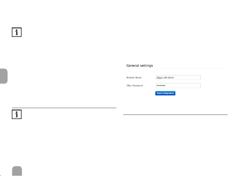
ÎEnter the desired password into the VBus Password
input eld.
ÎClick on Update Settings.
The new password is saved.
Accessing the device is not possible without the correct
password.
ÎNote down the new password and keep it carefully!
If the password is lost,the device has to be reset to the fac-
tory settings. For more information see page 9.
Fig. 8
Changing the module name
In the same menu, a new module name can be assigned to
the
Solar Manager Pro to LAN
interface adapter.The device
will be displayed with its module name in the network.
ÎEnter the desired name into the Module Name in-
put eld.
ÎClick on Update Settings.
The new module name is saved.

en
9
Reset
If the password for the
Solar Manager Pro to LAN
interface
adapter is lost, the device has to be manually reset to the
factory settings. In order to conduct a reset, proceed as
follows:
ÎOpen the housing (see page 4).
ÎPress the reset button for 5s.
During the reset process, the front-LED ashes red.
As soon as the reset is completed, the LED switches to a
permanent red.
ÎAs soon as the LED switches to a permanent red, re-
lease the reset button!
ÎWhen the reset has been completed, close the hous-
ing (see page 4).
The reset will set the device back to factory settings. All
adjustments made in the Web interface (see page 7) will
be lost and will have to be made again.
Accessing the VBus®/LAN interface adapter over
the Internet
Note
The DeviceDiscoveryTool cannot be used for nding
a
Solar Manager Pro to LAN
interface adapter over
the Internet.
The following preparations have to be made when a
Solar
Manager Pro to LAN
interface adapter connected to the
Internet via a router is to be accessed over the Internet:
ÎAssign a static address to the router.
ÎCarry out port routing in the router.
Assigning a static router address
In order to access the router and the
Solar Manager Pro to
LAN
interface adapter connected over the Internet,a static
address has to be assigned to the router.
There are 2 different ways to assign a static Internet ad-
dress to the router:
• Over a dynamic Domain Name Server (DynDNS)
• Over a static Internet IP address
Inhaltsverzeichnis
Sprachen:
Andere Resol Adapter Handbücher

Resol
Resol VBus/USB Bedienungsanleitung

Resol
Resol VBus Bedienungsanleitung

Resol
Resol VBus/EnOcean Interface adapter Bedienungsanleitung

Resol
Resol VBus/CANopen Bedienungsanleitung

Resol
Resol Vbus/LAN Bedienungsanleitung

Resol
Resol Vbus/LAN Bedienungsanleitung

Resol
Resol VBus/Modbus Bedienungsanleitung

Resol
Resol VBus/PWM Bedienungsanleitung

Resol
Resol VBus/PWM Bedienungsanleitung