
RoboLabs Grand Robopop 220 Bedienungsanleitung

Popcorn machine
Grand Robopop 220 (VPM-RGM2EU)
400 V 50 Hz
User manual
Read this manual before use and keep for future reference!
PDF version of this manual is available on www.robolabs.pro
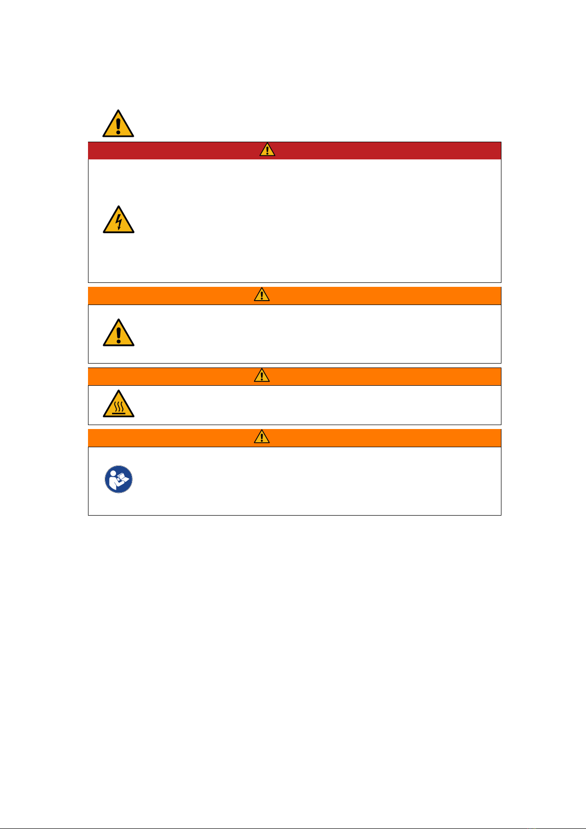
Safety requirements
This is the safety alert symbol. It is used to alert you to potential physical injury
hazards. Obey all safety messages that follow this symbol to avoid possible injury
or death.
DANGER
•Not grounded equipment can cause electric shock. Power outlet MUST
HAVE proper grounding to avoid electric shock.
•Using excessive water during cleaning can cause short circuit and elec-
tric shock. DO NOT USE excessive water or water jet for cleaning. DO
NOT SPILL water on electric panels or parts.
•ALWAYS unplug equipment before cleaning or servicing.
•No user serviceable parts inside. DO NOT OPEN electric panel unless you
are qualified for this.
WARNING
•DO NOT process other kernels than corn.
•DO NOT not leave running machine unattended.
•ALL swivel casters must be locked.
WARNING
•Machine’s surface might be HOT during the operation. Touching can
cause burn. DO NOT touch.
WARNING
•Improper installation, adjustment, alteration, service or maintenance can
cause property damage, injury, or death! Read and understand this man-
ual before use.
•Only instructed personnel is allowed to operate the equipment.
1

Contents
1 Overview 3
1.1 Technicalspecifications................................. 3
1.2 Deliveryset........................................ 3
1.3 Assembling and installation . . . . . . . . . . . . . . . . . . . . . . . . . . . . . . . 3
1.4 Powerrequirements................................... 3
1.5 Ambientconditions ................................... 4
1.6 Assembling........................................ 4
2 Design and principle of operation 5
2.1 Principleofoperation .................................. 5
2.2 Workingchamber .................................... 6
2.3 Controlpanel....................................... 7
2.4 Cornbinwithfeeder................................... 8
2.5 Modesofoperation ................................... 9
3 Intended use 10
3.1 Operatingorder ..................................... 10
3.2 Chamber clogged with popcorn . . . . . . . . . . . . . . . . . . . . . . . . . . . . 10
4 Settings 11
4.1 Poppingtemperature .................................. 11
4.2 Feedingtime ....................................... 11
4.3 Turbinespeed ...................................... 12
5 Popcorn quality 13
5.1 Rawcorn ......................................... 13
5.2 Moisturecontent..................................... 13
5.3 Productioncapacity ................................... 13
6 Maintenance and cleaning 14
6.1 Outersurface....................................... 14
6.2 Chamber ......................................... 14
6.3 Cornbinwithfeeder................................... 15
7 Transportation and storage 15
8 Quality control check 15
9 Warranty obligations 16
10 Manufacturer details 16
A Dimensions 17
2

1 Overview
Grand Robopop 220 VPM-RGM2EU is a hot-air popcorn making machine (hereinafter “ma-
chine”). It can process both Butterfly and Mushroom popcorn kernels. The machine is intended
for commercial use only.
1.1 Technical specifications
Throughput up to 100 kg/h
Hopper volume 25 kg
Rated voltage 3N 400 VAC
Rated frequency 50 Hz
Rated power 24 kW
Dimensions (LxWxH) 1220x810x1930 mm
Weight 300 kg
1.2 Delivery set
1x Machine
1x Electric compartment key
1x Cleaning brush
1x Spare halogen lamp
1x User manual
1x Technical manual
1.3 Assembling and installation
1. Unpack the package carefully and check the delivery set.
2. Remove protective film from all surfaces.
3. Wipe all surfaces with a clean soft cloth dampen with dish soap. Remove soap residues.
Wipe dry immediately.
4. Put the machine at even flat floor.
5. Lock all four swivel casters.
6. Connect to the power supply (see Power requirements section below).
1.4 Power requirements
DANGER
•Power outlet MUST have proper grounding to avoid electric shock.
•If supply cord damaged, it must be replaced by manufacturer, service
agent, or skilled person in order to avoid hazard!
•Connections must be done by skilled electrician ONLY!
•
Equipotential bonding wire (up to 10 sq.mm) shall be con-
nected to screw terminal on the base frame marked with IEC
5021 sign:
Use IEC 60309 3P+N+PE 63 A plug for connecting the machine. Short-circuit current rating
for the machine is 6 kA at 400 VAC.
3

1.5 Ambient conditions
The equipment is designed to be operated at the ambient temperature from +5°C to +40°C
(+41°F to +104°F) and relative humidity not more than 45% at 40°C (104°F) while using at
altitudes not exceeding 1000 m over the sea level. The temperature decreasing is related to
RH increasing, for example, 90% of RH at 20°C (68°F).
A ventilation hood measuring at least 1200x1200mm must be provided above the machine,
with a minimum capacity of 2500 cu.m/h. NOTE: Ambient conditions have strong impact on
the end product quality.
1.6 Assembling
1. Unpack the machine carefully.
2. Check the delivery set.
3. Remove protective film from all surfaces.
4. Wipe outer surfaces with a clean soft cloth dampened with a mild soap. Wipe dry imme-
diately.
5. Install on dedicated place. For space requirements see Appendix A.
6. Lock all four swivel casters.
NOTE: Each machine is tested at the factory with corn, some amount of corn kernels might be
found inside the chamber.
4

2 Design and principle of operation
2.1 Principle of operation
The machine and its main parts are represented on Fig.1. Principle of operation is the following.
Turbine (5) creates airflow circulating through the chamber (3), then to heating elements
area (6), and then back to the turbine. The direction of airflow is shown in red arrows.
Corn kernels are supplied from the corn bin with feeder (4) in the chamber.
Once popped, popcorn is being blown out of the chamber through the output port (1).
Operator uses control panel (2) to control the machine operation.
1
3
2
4
2
6
4
5
5
Figure 1: Main components
5

2.2 Working chamber
6
4
3
2
1
7
5
Figure 2: Chamber
Opened chamber is shown on Fig.2.
Perforated bowl (1) has special shaped holes, that
allow to create the air vortex as air flow comes in from
the turbine.
Corn kernels is fed into the chamber from the corn
supply tube outlet (4).
Chamber temperature sensor (2) constantly mea-
sures temperature in the chamber.
Optical sensor (3) controls corn movement inside
the chamber. Machine will not start next batch until
a batch of corn is completely processed, thus avoid-
ing chamber clogging with corn kernels and pop-
corn.
Bae (5) divides the chamber to separate the area
where corn kernels are being heated up, and the out-
put area.
Mesh screen (6) protects internal air ducts from be-
ing clogged with popcorn dust and scrap.
Back light (7) illuminates the chamber, so the op-
erator can visually control the process through the ob-
servation port in the chamber door.
6

2.3 Control panel
WARNING
•Using Emergency stop switch during normal operation might lead to
chamber clogging with popcorn, smoke formation, or machine failure.
USE EMERGENCY STOP SWITCH ONLY in case of emergency!
There are following items on control panel, see Fig.3:
1 – Turn o button; 2 – Pause button; 3 – Start button; 4 – Temperature regulator; 5 –
Clogging indicator; 6 – Low corn indicator; 7 – Feeding switch; 8 – Turbine switch; 9 – Heating
indicator; 10 – Popping indicator; 11 – Cooling indicator; 12 – Emergency stop button.
56
7
8
9
10
11
12
4
3
2
1
Figure 3: Control panel
Temperature regulator
Temperature regulator is used to control temperature
in the chamber.
Light indicators
CLOGGING – chamber is clogged
LOW CORN – corn is low or no corn.
HEATING – machine is in heating mode.
POPPING (glows) – machine is in operation mode.
POPPING (blinks) – machine is in pause mode.
COOLING – machine is in cooling mode.
Switches
FEEDING – weight of a single load.
TURBINE SPD – turbine speed increment.
Push buttons
START – turns machine on.
PAUSE – turns on pause mode and resume popping
mode.
TURN OFF – turns machine in cooling mode.
EMERGENCY STOP – immediately shuts the machine
o.
7

2.4 Corn bin with feeder
WARNING
•Burn hazard! Hot air may comes out from the machine through the corn
supply tube (pos.1 Fig.4). DO NOT touch or reach into the corn supply
tube. KEEP OFF this area.
Corn bin with feeder is shown on Fig.4.
Corn kernels is loaded in the corn bin (5). Inside there is a feeding auger, that is driven by
the motor (2). When the motor (2) operates, corn kernels are being pushed to the corn supply
tube (1) that directs corn kernels into the working chamber.
Protective fixed guard (3) prevents direct access to the exposed part of feeding auger.
Photoelectric sensor (4) trips whenever the bin becomes empty. Once the sensor is tripped,
the machine notifies the operator that the bin must be refilled.
2
4
1
3
5
Figure 4: Corn bin with feeder
8

2.5 Modes of operation
Whenever the machine is turned on, it is in one of the following modes of operation.
Heating mode
Once the machine is turned on, it automatically starts to heat up air in the chamber. Upon
reaching certain temperature the machine automatically switches to popping mode.
Popping mode
This is the main mode of operation. Machine processes corn kernels batch by batch, in cyclic
mode. Each cycle consists of three stages:
1. Feeding – hopper auger rotates, pushing corn kernels into the chamber.
2. Popping – corn kernels are being heated up in the chamber, eventually being blown out
from the chamber once popped.
3. Purging – turbine is accelerated in order to blow out everything left in the chamber: un-
popped kernels, dust and other scrap.
Pause mode
Whenever the operator initiates pause, the machine processes current batch of corn, and then
stop feeding next batches of corn. The temperature in the chamber is maintained at the set
value. Popping process can be resumed at any time.
Cooling mode
The machine needs to be cooled down before turning the turbine o. Whenever the opera-
tor initiates cooling mode, heating elements are de-energized; but the turbine keeps running,
cooling down the machine. Once temperature drops low enough, the turbine stops and the
machine turns o automatically.
9
Dieses Handbuch passt für folgende Modelle
1
Inhaltsverzeichnis
Andere RoboLabs Küchengerät Handbücher

RoboLabs
RoboLabs TWISTER-M2 Bedienungsanleitung

RoboLabs
RoboLabs ROBOJETFLOSS Bedienungsanleitung

RoboLabs
RoboLabs ROBOMIX MINI Bedienungsanleitung

RoboLabs
RoboLabs MINI ROBOPOP 25 Bedienungsanleitung

RoboLabs
RoboLabs ROBOPOP 60 Bedienungsanleitung

RoboLabs
RoboLabs ROBOJETFLOSS ACB-09-120 Bedienungsanleitung

RoboLabs
RoboLabs ROBOJETFLOSS Bedienungsanleitung

RoboLabs
RoboLabs Robopop 75 Bedienungsanleitung

RoboLabs
RoboLabs SUGARLIPS 20 Bedienungsanleitung

RoboLabs
RoboLabs VPM-RGM2 Bedienungsanleitung


