
ROLA-CHEM Pro Series Bedienungsanleitung

ROLA-CHEM
®
Pro Series Pump PN 522105 07/10/2019 Page: 1 of 12
PRO SERIES PUMP
Installation & Parts Manual
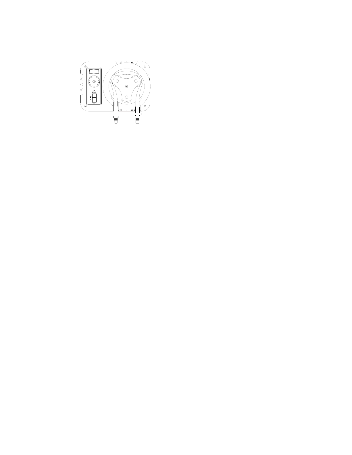
INLET OUTLET
Section title Page
1. Safety Instructions 2
2. Specifications 3
3. Installation 4
4. Operation 5
5. Maintenance 5
6. Chemical Feed Pump Size Guide 8
7. Troubleshooting 9
8. Parts List 10
9. Warranty and Service 12
IMPORTANT SAFETY INSTRUCTIONS
READ AND FOLLOW ALL INSTRUCTIONS
SAVE THESE INSTRUCTIONS

ROLA-CHEM® Pro Series Pump PN 522105 07/10/2019 Page: 2 of 12
1. SAFETY: When installing and using this electrical equipment, basic safety
precautions should always be followed, including:
1.1 WARNING! To reduce the risk of injury, do not permit children to use this product unless
they are closely supervised at all times.
1.2 WARNING! Risk of electric shock.
Connect only to a grounding type receptacle protected by a ground-fault circuit interrupter
(GFCI). Contact qualified electrician if you cannot verify that the receptacle is protected by a
GFCI and that your installation meets local electrical codes, including grounding of water
system components.
1.3 WARNING! Risk of electric shock.
Do not bury or modify the metering pump cord. Locate cord to minimize abuse from lawn
mowers, hedge trimmers, and other equipment.
1.4 WARNING! Risk of electric shock.
On cord and plug-connected units, replace a damaged cord immediately.
1.5 WARNING! Risk of electric shock.
Do not use extension cord to connect unit to electrical supply; provide a properly located
outlet.
1.6 WARNING! Risk of electric shock.
Do not install within an outer enclosure or beneath the skirt of a hot tub or spa unless so
marked. All instructions must be in accordance with appropriate electrical codes.
1.7 WARNING! Risk of electric shock/pinching/chemical exposure.
Remove power sources or lockout circuit prior to performing maintenance on metering pump.
Pumps are usually timer controlled and can start at any time.
1.8 WARNING! Risk of Chemical Overdose/Exposure.
Removing power from circulating pump must also remove power from the chemical injection
pump. Provide a properly located outlet controlled by the circulating pump circuit.
1.9 WARNING! Risk of Chemical Overdose/Exposure.
Use a device such as a flow switch to shut off power from the from the chemical injection
pump in the event of pool pump or circulation failure.
It is not safe to automatically dispense chemicals into a circulating system that is not running.
1.10 WARNING! Risk of Chemical Overdose/Exposure.
Minimize amount of chemical on site that is available to dispense.
Size the feeder and container to pool/spa capacity.
Dilute chemical for small bodies of water.

ROLA-CHEM® Pro Series Pump PN 522105 07/10/2019 Page: 3 of 12
1.11 WARNING! Risk of Chemical Exposure.
Depressurize the system prior to connecting or disconnecting the metering pump.
1.12 CAUTION! Wear protective clothing, gloves and safety glasses at all times when
working on or near the metering pump.
1.13 CAUTION! Install the metering pump and chemical containers in a ventilated secured
location. Protect children, pets, and property from chemical hazards. Containment and/or
wash down capability must be in accordance with local regulations and chemical suppliers’
instructions.
1.14 CAUTION! Read and follow all instructions supplied with the chemical being fed. User is
responsible for determining the compatibility of the chemical with the metering pump.
Consult supplier of chemical if use and handling instructions are not available.
1.15 CAUTION! This pump is for use with permanently installed pools and may also be used
with hot tubs and spas. Do not use with storable pools. A permanently installed pool is
constructed in or on the ground or in a building such that it cannot be readily disassembled
for storage. A storage pool is constructed so that it is capable of being readily disassembled
for storage and reassembled to its original integrity.
1.16 CAUTION! Service tubing regularly, e.g. when refilling chemical container. See
OPERATION and MAINTENANCE sections for details.
2. Specifications
Power: 120 volt AC (corded) or 240 volt AC (conduit), 50/60 HZ, 2.5 amp (max.)
Pressure / suction: 30 psi max. dispense line pressure. RC503 maximum dispense line
pressure is 25 psi. 18 foot max. inlet suction lift
Capacity: Estimated gallons per day
SETTING ON OFF RC252 RC25/53 RC103 RC503
LO 4 SEC 9 MIN 0.01 0.10 0.34 1.00
2 1.5 MIN 7.5 MIN 0.18 1.20 3.72 8.88
3 3 MIN 6 MIN 0.33 3.60 10.8 24.0
4 4.5 MIN 4.5 MIN 0.50 6.00 19.4 40
5 6 MIN 3 MIN 0.66 8.40 25.2 53
6 7.5 MIN 1.5 MIN 0.78 11.0 33.4 67
HI 9 MIN 4 SEC 0.90 12.0 38 77
Capacity in this table is intended as a guide. Actual output may vary based on actual
environment.

ROLA-CHEM® Pro Series Pump PN 522105 07/10/2019 Page: 4 of 12
3. Installation Tools required – Phillips screwdriver & adjustable wrench,
23/32” drill & ½” pipe tap (NPT) or 7/16” drill & ¼ “ pipe tap (NPT)
3.1 Install the ROLA-CHEM® pump in an area protected from natural elements (sun, rain,
freezing, etc.).
Environmental effects may increase required service and maintenance.
The inlet side of the pump must be above the incoming liquid and the chemical container.
Flooded suction is not required or recommended.
Ensure that the tube can be routed without allowing it to kink.
Do not install directly above the chemical container or other equipment that can be
damaged by chemicals. Wall mounting key slots are provided on the rear of the pump
enclosure (6.25” apart for #10 screws).
Comply with local health codes. Cross connections must not allow undesired chemical
treatment.
3.2 For chlorine pumps, undiluted swimming pool grade 15% maximum sodium hypochlorite
may be used. For acid pumps, 32% maximum hydrochloric acid may be used. Black
Norprene Pinch Tube is included for use with hydrochloric acid. See sizing for dilution.
3.3 Connect the injection fitting into the line to be treated. This should be after the heater. Use
pipe tape to seal the pipe threads. Do not exceed pressure / suction specifications.
A check valve may be used at the point of injection to prevent backflow, then the tubing
assembly can be disconnected at its connection to the check valve and it will not be
necessary to plug the injection fitting hole.
For installation where pressure is greater than 20 psi, use a check valve as the injection
fitting or in-line before injection fitting. One 3/8 barbed check valve and one 3/8 barbed inlet
x ¼ NPT (American National Standard Taper Pipe Thread) outlet check valve are included
with standard pumps. Use tubing clamp over tube on barbed ends of fitting on outlet side
of pump.
For low pressure applications, a brass injection fitting will fit a ½ NPT connector or a ½
NPT hole tapped into heavy gage pipe. Push the vinyl tube through the fitting until it hits
the bottom of the pipe, then pull it back about ¼ inch. This creates an outlet for chlorine
away from the injector fitting and helps the injector fitting from becoming clogged.
For installations where a ¼ NPT injection port connection is already available, a ¼ NPT
adapter with a tubing clamp is included in the literature kit.
CAUTION! Do not install injection fitting directly into copper lines (may cause corrosion
and discoloring).
3.4 Place the suction tubing in the chemical container with the weight lying on its side. This
will keep the end of the suction tubing off the bottom to allow for sediment.
3.5 Electrical hook-up must comply with Code, including safety devices. Voltage must be per
the data plate.

ROLA-CHEM® Pro Series Pump PN 522105 07/10/2019 Page: 5 of 12
CAUTION! Pump must be wired to prevent overdosing. Connect pump to turn off when
circulating system is off. Connect pump power to a flow switch on the return piping (if
circulation system stops, chemical pump must stop).
CAUTION! Pump must be turned off when backwashing filters.
4. Operation
4.1 Before placing the ROLA-CHEM® pump in operation, lubricate the Pinch Tube with silicone
lubricant (supplied in the literature kit) and install per Pinch Tube Assembly replacement
instruction section 5.2. NOTE: Maintain lubrication on the Pinch Tube at all times. Intervals
for applying lubrication vary with pump size, frequency of operation and pressures.
To access the Pinch Tube Assembly, remove the knob from the front of the pump housing.
Rotate the housing cover counterclockwise and lift off the cover, or on the RC252 Models
remove wing nuts and lift off the body half. Reverse steps to reassemble.
CAUTION! Remove power from pump when lubricating Pinch Tube. Do not remove Pinch
Tube Assembly from pump housing while system is under pressure.
4.2 The three-way switch has TIMER, CONTINUOUS and OFF positions. For interrupting
action, use the TIMER position and adjust the timer knob for the desired output. For use with
a controller (and for continuous, non-stop chemical feeding) use the CONTINUOUS position.
TIMER reduces the output by interrupting the chemical feeding for the selected portion of its
nine minute timing cycle (setting of 4 provides approximately 4.5 minutes on and 4.5
minutes off). The pump will feed at its maximum rate relative to operating conditions
whenever it is feeding. Where an extremely accurate feeding setting is required, use a
calibrated cylinder and a stopwatch to calculate the amount fed under actual operating
conditions. Be sure to use full timer cycles when making the calculations. See rate chart for
nominal feed rate settings.
CONTINUOUS runs the pump at maximum feed rate regardless of the timer knob position.
5. Maintenance
5.1 Preventive maintenance is the best defense against possible leaks. Inspect tubing
frequently as stated in safety instructions and lubricate Pinch Tube often to maintain a
coating of silicone grease. Pinch Tube is designed for minimum service life of 500 hours
pump run time. However Pinch Tube life is affected by many factors such as system back
pressure, environmental temperature, and the chemical being pumped. Replace the Tube
Assembly when found to be deteriorating or at the start of a new season.
CAUTION! Both inlet and outlet connections may be under pressure. Depressurize the
system prior to connecting or disconnecting the metering pump.
WARNING! Pump tubing may contain chemicals. Wear protective clothing, gloves and
safety glasses at all times when working on or near the metering pump.

ROLA-CHEM® Pro Series Pump PN 522105 07/10/2019 Page: 6 of 12
WARNING! Severe pinching of fingers can occur while installing Pinch Tube Assembly.
Caution must be used to keep fingers away from rotating parts.
5.2 Pinch Tube Assembly replacement procedure
1) See OPERATION section 4.1 to access Pinch Tube Assembly.
Figure 1
Inlet
2) Jog switch intermittently between OFF and CONTINUOUS positions to move Roller to
position as shown in Figure 1 then switch OFF. Roller will rotate clockwise when switch
is in CONTINUOUS position.
3) Pull lower left end of Pinch Tube Assembly out of inlet port (as noted in Figure 1) and
continue to pull away from Roller. Jog switch intermittently between OFF and
CONTINUOUS positions to move Roller. Keep fingers away from rotating parts. Tube
will be released as Roller rotates.
Figure 2
4) To install new Pinch Tube, Jog switch intermittently between OFF and CONTINUOUS
positions to move Roller to position as shown in Figure 2 then switch OFF.
5) Lubricate Pinch Tube Assembly as noted in OPERATION section 4.1. Lay inlet end
(without clamp) in inlet port on left with about ¾” of Pinch Tube protruding from
housing. See Figure 2.
Figure 3 Figure 4
ROLA-CHEM® Pro Series Pump PN 522105 07/10/2019 Page: 7 of 12
6) Jog switch intermittently between OFF and CONTINUOUS positions to rotate Roller
assembly while guiding Pinch Tube Assembly into housing as shown in Figures 3 and
4 then switch OFF with roller in position as shown in Figure 4. Keep fingers away from
rotating parts.
Figure 5
7) With switch OFF, lay Pinch Tube Assembly in outlet port as shown in Figure 5.
8) Reassemble housing cover.
5.3 Remove the Pinch Tube Assembly when the pump is not in use. Place the Pinch Tube
Assembly in a clean poly bag when not in use. The pump shipping bag may be saved for
this purpose. A Pinch Tube Assembly under light duty may last more than one season, but
replacing the Pinch Tube Assembly may prevent damaging the pump or an unscheduled
maintenance call.
5.4 Crystal buildup is seldom a problem with ROLA-CHEM® pumps. However, it may be
necessary to flush the pump tubing. Use plain water or a weak solution of muriatic acid (1/2
pint muriatic acid to one gallon of water).
WARNING! Always add acid to water. Never add water to acid. (e.g. fill container with one
gallon of water then add 1/2 pint of acid) Wear protective clothing, gloves and safety
glasses.
Additional preventative maintenance may be required in harsh environments. Strong
chemicals and chemical vapors may cause corrosion of metal components. Inspect pumps
for corrosion to exposed metal components. For pumps utilizing timer functions,
replacement of the timer/pot assembly is recommended after five years.

ROLA-CHEM® Pro Series Pump PN 522105 07/10/2019 Page: 8 of 12
6. Chemical Feed Pump Size Guide
WARNING! Failure to use proper size feeder may result in injury.
Pump size must be in compliance with local health codes. When in doubt about pump size
or if different brand feed pumps are used, consult your supplier or ROLA-CHEM®.
NOTE: ORP/pH controllers will not function properly with an over or undersized feeder.
SPA POOL CHLORINE
PUMP
ACID
PUMP
Capacity (Gallons) (Capacity, Gallons)
500-2,500 2,500-5,000 RC 252
(0.9 GPD)
SEE NOTE*
2,500-25,000 5,000-65,000 RC 25/53
(12GPD)
SEE NOTE*
65,000-200,000** RC 103
(38 GPD)
RC 25/53
(12 GPD)
180,000-400,000** RC 503
(77 GPD)
RC 25/53
(12 GPD)
Sizing chart is only a guide and is based on ROLA-CHEM® or equivalent pumps using
10.5% sodium hypochlorite (chlorine) or 20-32% hydrochloric acid (muriatic acid).
*Consider diluting chemicals for small bodies of water. Required pump size may vary when
diluting chemicals. Size pumps based on dilution ratio and available pump sizes. Typical
dilution ratios for muriatic acid range from 4:1 to 9:1. When feeding acid diluted 9:1, the acid
pump may be the same size as the chlorine pump.
WARNING! Always add acid to the water. Never add water to acid. (e.g. fill tank with four
gallons of water then add one gallon of acid) Wear protective clothing, gloves, and safety
glasses.
**RC 103 pumps have been used on pools up to 240,000 gallons (RC 503 pumps to
500,000 gallons).

ROLA-CHEM® Pro Series Pump PN 522105 07/10/2019 Page: 9 of 12
7. Troubleshooting Pump Problems
Issue Cause
A
ction
Pump does not operate,
no noise, no motion.
Power
Check power source, switches, circu
box, ground fault tripping, etc.
Pump will not shut off with
switch in TIMER position.
Switch or timer
Check switch continuity and
replace if faulty. If switch has no
continuity in off position and pump
will not shut off, replace timer.
Pump motor turning but no
movement in roller
assembly.
Motor gearbox Replace motor.
Short Pinch Tube life. Worn or loose
components
Replace worn roller assembly or
gearbox assembly and secure
pump housing and cover.
Lubrication Lubricate Pinch Tube more
frequently.
High System pressure
Discoloration
Check that system pressure is 30
psi max. (RC503 25 psi max.).
Tubing discoloration does not
affect performance. Tubing can be
replaced if desired.
Pump rotating but not
pumping fluid.
Pinch Tube Assembly Replace Pinch Tube Assembly.
Roller assembly Replace roller assembly.
Motor bearings Replace motor.
Pump motor starts and
stops with switch in
CONTINUOUS position.
High temperatures Check fan and replace if damaged.
Improve ventilation to pump.
Switch Replace switch.

ROLA-CHEM® Pro Series Pump PN 522105 07/10/2019 Page: 10 of 12
8. Parts List
ITEM PART No. DESCRIPTION MODEL
RC252 RC25/53 RC103 RC503
1 527255 ENCLOSURE COVER NS X X X X
2 527251 ENCLOSURE BODY NS X X X X
3 525253 SCREW 10-24 x 4-1/2 PPH STL ZP X X X X
4 521752 HOUSING, BODY X X X
5 521751 HOUSING, COVER X X X
6 523408 KNOB, LOCK ASSY X X X
7 523400 ROLLER, TRI NS-ASSY (3 ROLLER) X X X
8 525233 SCREW 10-24 x 3/4 PTH SST X X X
9 521225 HOUSING, PUMP X
10 525004 BRASS STUD 10-32 X
11 525140 WING NUT 10-32 X
12 523332 ROLLER, 2 INCH H-BLOCK X
13 521058 GEAR MOTOR, 1 RPM, 120V 120 V
521094 GEAR MOTOR, 1 RPM, 240V 240 V
521805 GEAR MOTOR, 4 RPM, 120V 120V
521806 GEAR MOTOR, 4 RPM, 240V 240V
521316 GEAR MOTOR, 16 RPM, 120V 120V
521317 GEAR MOTOR, 16 RPM, 240V 240V
524756 GEAR MOTOR, 30 RPM, 120V 120V
524755 GEAR MOTOR, 30 RPM, 240V 240V
14 524752 FAN, 2.5 INCH X X X X
15 524065 TIMER/POT ASSY 120 V ALL 120 V PUMPS
524066 TIMER/POT ASSY 240 V ALL 240 V PUMPS
16 521154 KNOB, TIMER X X X X
17 524711 SWITCH ASSY, 3 WAY X X X X
18 523252 TUBE ASSY-TYGON/VINYL 8 INCH NOTE A X
523118 TUBE ASSY-TYGON/VINYL 13.5 INCH NOTE A X X X
523414 TUBE ASSY-NORPRENE/VINYL 8 INCH NOTE A X
523140 TUBE ASSY-NORPRENE/VINYL 13.5 INCH NOTE A X X X
19 523250 TYGON PINCH TUBE ASSY-8 INCH NOTE B X
523115 TYGON PINCH TUBE ASSY-13.5 INCH NOTE B X X X
523251 NORPRENE PINCH TUBE ASSY-8 INCH NOTE B X
523114 NORPRENE PINCH TUBE ASSY-13.5 INCH NOTE B X X X
20 523102 LUBRICANT, E-Z GLIDE, 3GRAM X X X X
21 525114 CLAMP, HOSE #8 (LARGE) X X X X
22 520111 FITTING, HOSE CONNECTOR, 3/8 BARB X X X X
23 520110 CLAMP, HOSE #6 (SMALL) X X X X
24 520120 TUBING, VINYL .31 x .44 x 66 INCH X X X X
520116 TUBING, VINYL .31 x .44 x 100 FOOT (OPTIONAL)
25 523110 WEIGHT, HOSE 7/16 X X X X
26 520112 RETAINER-HOSE WEIGHT X X X X
27 527158 BRASS INJECTION FITTING, 1/2" MNPT X X X X
28 525113 SEAL, INJECTION FITTING (SPARE) X X X X
29 520113 ADAPTER, PP1/4MNPT x 3/8 BARB X X X X
30 521170 CHECK VALVE, PVC, 3/8 BARB x 1/4 NPT X X X X
31 521160 CHECK VALVE, PVC, 3/8 x 3/8 BARB X X X X
32 524155 POWER CORD, 18-3SJT, 120V PUMP-CORDED,120 V
524156 POWER CORD, 18-3SJT, 240V PUMP-CORDED,240 V
33 524090 STRAIN RELIEF CORDED PUMPS
34 524115 J-BOX
35 524135 LOCK NUT, STEEL 1/2 CONDUIT MODELS
36 524110 NIPPLE, 1/2 x 1
37 525214 GROUND SCREW #8, GREEN X X X X
38 8110030 LOCK WASHER (GROUND SCREW) X X X X
39 527159 FITTING, INJECTION-8M,NYLON (OPTIONAL)
NOTE A: COMPLETE TUBE ASSEMBLY
ITEM 18 INCLUDES: PINCH TUBE ASSEMBLY (ITEM 19) AND ITEMS 23 THRU 27
NOTE B: PINCH TUBE ASSEMBLY
ITEM 19 INCLUDES: TYGON (OR NORPRENE) PINCH TUBE, CLAMP (ITEM 21) AND FITTING (ITEM 22)
Inhaltsverzeichnis
Andere ROLA-CHEM Wasserpumpe Handbücher

Beliebte Wasserpumpe Handbücher anderer Marken


Sykes AmeriPumps
Sykes AmeriPumps GP100M Fehlerbehebungshandbuch

DUROMAX
DUROMAX XP WX Series Bedienungsanleitung

BRINKMANN PUMPS
BRINKMANN PUMPS SBF550 Bedienungsanleitung

Franklin Electric
Franklin Electric IPS Bedienungsanleitung

Xylem
Xylem e-1532 Series Bedienungsanleitung

Milton Roy
Milton Roy PRIMEROYAL Bedienungsanleitung