
SanDisk APW-895N/IP-420 Bedienungsanleitung

APW-895N/IP-420
INSTRUCTION MANUAL
* "CompactFlash(TM)" is the registered trademark of SanDisk Corporation, U.S.A.

i
CONTENTS
I. CAUTIONS BEFORE OPERATION.................................................................................. 1
II. CONFIGURATION OF THE MACHINE ........................................................................... 2
III. SPECIFICATIONS........................................................................................................... 3
1. MECHANICAL SPECIFICATIONS ..........................................................................................................3
2. ELECTRICAL SPECIFICATIONS............................................................................................................3
IV. INSTALLATION............................................................................................................... 4
1. REMOVING PACKING MATERIALS.......................................................................................................4
2. SECURING THE MACHINE.....................................................................................................................4
3. CONNECTING THE FOOT PEDAL......................................................................................................... 5
4. CONNECTING THE AIR COUPLER ......................................................................................................5
5. CONNECTING THE POWER PLUG .......................................................................................................6
6. ASSEMBLING THE THREAD STAND AND ATTACHING IT TO THE MACHINE .................................. 7
7. INSTALLING SP-46N (CLAMP BAR STACKER) (OPTIONAL PART NO. : 40149301) ........................ 8
8. INSTALLING SP-47N (ROLLER STACKER) (OPTIONAL PART NO. : 40149302) ............................... 9
9. REMOVING THE HEAD FIXING PLATE ............................................................................................... 10
10. INSTALLING THE SUB-TABLE ..........................................................................................................10
11. INSTALLING OPERATION PANEL IP-420..........................................................................................10
12. LUBRICATING THE OIL TANK ........................................................................................................... 11
13. INSTALLING SA-120N (INTERLINING SUPPLYING DEVICE)
(OPTIONAL PART NO. : 40149798) .....................................................................................................12
14. ADJUSTMENT OF SA-120N (INTERLINING SUPPLYING DEVICE)
(OPTIONAL PART NO. : 40149798) .....................................................................................................13
V. PREPARATION OF THE SEWING MACHINE .............................................................. 14
1. HOW TO OPERATE THE SEWING MACHINE HEAD..........................................................................14
(1) How to attach the needles ...............................................................................................................14
(2) Thread used.....................................................................................................................................14
(3) How to pass the needle thread ........................................................................................................15
2. HOW TO REMOVE THE SEWING TABLE............................................................................................ 16
(1) When replacing the bobbin thread...................................................................................................16
(2) Cautions to be taken when the sewing tables are removed ............................................................ 17
3. HOW TO WIND THE BOBBINS ............................................................................................................18
4. HOW TO THREAD THE BOBBIN CASE ..............................................................................................19
5. HOW TO INSTALL THE BOBBIN CASE............................................................................................... 19
6. HOW TO ADJUST THE THREAD TENSION ........................................................................................ 20
7. SETTING THE MATERIAL TO BE SEWN............................................................................................. 21
8. ADJUSTING THE MATERIAL GUIDE ...................................................................................................21
VI. HOW TO USE THE OPERATION PANEL.................................................................... 22
1. PREFACE ..............................................................................................................................................22
2. BASIC OPERATION OF THE OPERATION PANEL (IP-420)...............................................................25
(1) Conguration of IP-420....................................................................................................................25
(2) Buttons used in common ................................................................................................................. 26
(3) Basic operation ................................................................................................................................26
3. EXPLANATION OF THE BASIC SCREEN............................................................................................29
(1) Input screen (Independent sewing mode)........................................................................................29
(2) Sewing screen (Independent sewing mode) ...................................................................................30

ii
(3) Input screen (Alternate sewing mode) .............................................................................................31
(4) Sewing screen (Alternate sewing mode) ......................................................................................... 32
(5) Input screen (Cycle sewing mode)...................................................................................................33
(6) Sewing screen (Cycle sewing mode) ..............................................................................................34
4. USING THE COUNTER .........................................................................................................................35
(1) Setting procedure of the counter......................................................................................................35
(2) Releasing procedure of count-up.....................................................................................................38
(3) Counter value changing procedure during sewing .......................................................................... 38
5. USING THE BOBBIN THREAD AMOUNT ADJUSTMENT COUNTER................................................ 39
(1) Setting procedure of the bobbin thread remaining amount adjustment counter .............................. 39
(2) Releasing procedure of the bobbin thread remaining amount detection count-up .......................... 41
6. CHANGING THE SEWING MODE ........................................................................................................42
7. USING THE SEWING PATTERN...........................................................................................................43
(1) Performing the selection of pattern..................................................................................................43
(2) Performing the new creation of pattern............................................................................................44
(3) Copying the pattern..........................................................................................................................45
(4) Erasing the pattern...........................................................................................................................47
(5) Naming the pattern ..........................................................................................................................48
(6) Editing procedure of the cycle sewing data ..................................................................................... 49
8. CHANGING THE SEWING DATA.......................................................................................................... 51
(1) Changing procedure of the sewing data ..........................................................................................51
(2) Sewing data list................................................................................................................................52
9. CHANGING THE MEMORY SWITCH DATA ......................................................................................... 60
(1) Changing procedure of the memory switch data ............................................................................. 60
(2) Memory switch data list....................................................................................................................61
10. PERFORMING OPTIONAL SETTING................................................................................................. 69
(1) Changing procedure of the optional setting .....................................................................................69
(2) Optional setting list...........................................................................................................................70
11. CHANGING THE DEVICE SETTING................................................................................................... 71
(1) Changing procedure of the device setting ....................................................................................... 71
(2) Device setting list.............................................................................................................................72
12. CUSTOMIZING THE PEDAL OPERATION .........................................................................................73
(1) Method to select and use the customized data................................................................................73
(2) Customizing the pedal operation data ............................................................................................. 74
13. CUSTOMIZING THE DATA INPUT SCREEN......................................................................................76
14.
PERFORMING THE CUSTOMIZING SETTING OF THE SEWING SCREEN ...................................................... 78
15. USING THE INFORMATION................................................................................................................80
(1) Observing the maintenance inspection information......................................................................... 81
(2) Releasing procedure of the warning ................................................................................................82
(3) Observing the production control information .................................................................................. 83
(4) Performing setting of the production control information ................................................................. 85
(5) Observing the operation measurement information......................................................................... 87
16. USING THE COMMUNICATION FUNCTION ......................................................................................89
(1) Handling possible data ....................................................................................................................89
(2) Performing communication by using the media...............................................................................89
(3) Performing communication by using USB ....................................................................................... 89
(4) Take-in of the data ...........................................................................................................................90
(5) Take-in of plural data together .........................................................................................................91
17. PERFORMING FORMATTING OF THE MEDIA..................................................................................93

iii
VII. MAINTENANCE........................................................................................................... 94
1. INSPECTION .........................................................................................................................................94
(1) Maintenance and inspection of the pneumatic device ..................................................................... 94
(2) Maintenance and inspection related to the sewing machine ........................................................... 94
(3) With regard to the waste oil of the hook oil......................................................................................95
(4) With regard to the cleaning of the hook shaft base.......................................................................... 95
2. MARKING LIGHT...................................................................................................................................96
(1) Fixed marking (standard).................................................................................................................96
(2) Movable marking (optional)..............................................................................................................96
(3) Adjusting the marking light irradiation position.................................................................................97
3. REPLENISHING GREASE TO THE DESIGNATED PLACE................................................................. 98
4. CONSUMABLE REPLACEMENT COMPONENTS.............................................................................100
5. TILTING THE MACHINE......................................................................................................................102
6. STANDARD OF REPLACING TIME OF THE GAS SPRING .............................................................. 103
7.
REPLACING PROCEDURE BETWEEN DOUBLE-WELT AND SINGLE-WELT ........................................................104
(1) Replacing procedure between double-welt and single-welt........................................................... 104
(2) Fine adjustment of the position of garment body clamp ................................................................ 104
(3) Replacing the binder......................................................................................................................105
8. ADJUSTING THE CORNER KNIFE ....................................................................................................106
9.
ADJUSTING THE POSITION OF THE SENSOR FOR DETECTING FLAPS..................................................... 107
10.
CAUSES AND CORRECTIVE MEASURES AGAINST TROUBLES WITH THE BOBBIN THREAD REMAIN-
ING AMOUNT DETECTING DEVICE .................................................................................................................... 108
11. HOW TO ADJUST THE FOOT PEDAL ............................................................................................. 109
12. ERROR CODE LIST .......................................................................................................................... 111
13. INPUT NUMBER TABLE ................................................................................................................... 121

− 1 −
I. CAUTIONS BEFORE OPERATION
Following items have to be checked every working day before the operation of the machine
and before the start of work hours.
1. Ascertain that the sewing machine is lled with the predetermined amount of oil.
2. Never operate the machine unless the lubricating part in the hook has been lled up with oil.
3. Ascertain that the pressure gauge indicates the designated air pressure of 0.5 MPa.
*
(This is necessary particularly when the compressor is stopped for a lunch break or the like.)
If the compressed air pressure is equal to or less than the designated value, troubles such as
interference between the parts can occur. It is therefore necessary to carefully check the com-
pressed air pressure.
4. Check whether the needle thread/bobbin thread need to be replenished.
5. To perform sewing immediately after turning ON the power switch, perform trial stitching rst,
then proceed with sewing of actual products after the test sewing.
6. In order to prevent the optical ber sensor of the bobbin thread remaining amount detecting de-
vice from showing a detecting failure, be sure to clean thread waste around the hook using an air
gun once or more times a day.
7. In order to protect the ap sensor from showing a detecting failure, be sure to clean dust on the
reecting tape of the folding plate using an air gun once or more times a day.
− 2 −
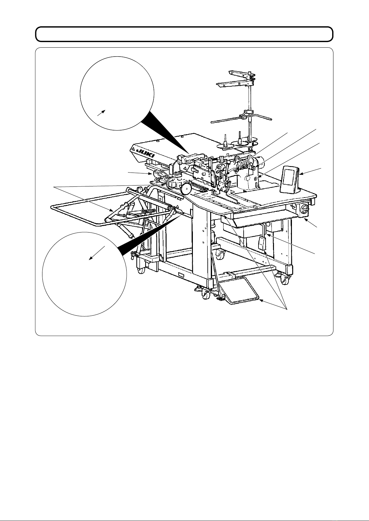
II. CONFIGURATION OF THE MACHINE
The APW-895N consists mainly of the following units.
A Frame and structural components (Framesewing table, covers, foot switch, etc.)
B Clamp foot unit and feed mechanism
C Corner knife unit
DBinder unit (Binder components and its driving components)
E Pneumatic control unit (Pneumatic control devices and pipings)
FStacker unit (Optional)
GSewing machine head
HElectric control unit (Control panel)
IOperation panel
J Power switch (Also used as the emergency stop switch)
K Temporary stop switch
With this machine consisting of the aforementioned 11 units, you can do desired welting work simply by set-
ting materials (garment body, interlining piece, welting patch, etc.) in place and operating the switches on the
operation panel.
In addition, when temporary stop switch K is pressed during operation of the device, the device stops.
DK
I
B
A
J
F
E
G
H
C

− 3 −
III. SPECIFICATIONS
1. MECHANICAL SPECIFICATIONS
1 Sewing machine LH-895N model of 2-needle, lockstitch machine with a center knife
2 Sewing speed 3,000 sti/min (max.)
3 Stitch length Lockstitch : 2.0 to 3.4 mm (standard : 2.5 mm)
Condensation stitch : 0.5 to 1.5 mm (standard : 1.0 mm)
Back tack stitch : 0.5 to 3.0 mm (standard : 2.0 mm)
Condensation/Back tack stitch selectable
4Types of welt Parallel double welt,
parallel single welt Each with ap or without ap
5Pocket lip length
(Welt lenght)
Standard type : Possible to set in increments of 1 mm within the range of min. 18 to
max. 220 mm
Note that the pocket length is min. 35 mm when using the corner knife.
(Min. 50 mm in case of 14 mm gauge or more, and min. 21 mm by adding a solenoid valve)
For the long and wide type : Possible to set in increments of 1 mm within the range of
min. 18 to max. 250 mm
Note that the pocket length is min. 70 mm when using the corner knife. (Min. 56 mm by add-
ing a solenoid valve)
Possible to set max. 300 mm without entering corner knife.
6 Welting width
(Needle gauge)
8, 10, 12, 14, 16, 18 and 20 mm ( Long and wide type : 22, 24, 26, 28, 30 and 32 mm)
* However, for with dart stretcher, 8, 10, and 12 mm
For with zipper attachment, 16 mm, 18 mm, 20 mm
7 Needles ORGAN DP X 17 #14 to #18 (standard #16)
8 Thread Spun thread #60 (Recommended)
9 Hook Full rotary, vertical-axis, self-lubrication hook
10 Thread take-up lever Slide thread take-up lever
11 Needle bar stroke 33.3mm
12 Cloth feed mechanism Driven by stepping motor
13 Control By a micro-computer
14 Safety mechanism Machine operation is automatically stopped if the cloth feed mechanism error detector,
the needle thread breakage detector or any of the various safety devices is actuated.
15 Lubricating oil JUKI New Defrix Oil No. 1
16 Operating air pressure 0.5 MPa
17 Air consumption Approx. 40 Nℓ/min
18 Dimensions of machine Width : 1,095 mm
(1,580 mm - when including the stacker)
Length : 1,500 mm
Height :
1,165 mm
(1,800 mm - when including the thread stand)
19 Weight 238.5kg
20 Noise - Equivalent continuous emission sound pressure level (LpA) at the workstation :
A-weighted value of 78.5 dB; (Includes KpA = 2.5 dB); according to ISO 10821- C.6.3
-ISO 11204 GR2 at 3,000 sti/min for the sewing cycle, 4.5s ON.
(Pattern : No.1, Jump feed speed of clamp foot : Max speed).
2. ELECTRICAL SPECIFICATIONS
1The number of independent sewing patterns that
can be stored in memory 99 (1 to 99)
2The number of alternate sewing patterns that can be
stored in memory 20 (1 to 20)
3The number of cycles that can be stored in memory 20 (1 to 20)
4 Input power : Single phase : 220 to 240V 50/60 Hz
3-phase : 200 to 240V 50/60 Hz (Optional 380V)
Voltage uctuation : Within + 10% of the rated voltage
5Power consumption 270VA

− 4 −
IV. INSTALLATION
Remove the upper cover and remove
the string and packing materials that
have xed the clamp foot.
Remove the string and packing
materials that have xed the clamp
bar stacker.
Remove the string that has xed the
binder unit.
Draw out the corner knife unit and
remove the string that has xed the
unit. Cut and remove the clip band that
has xed the needle bar.
1. REMOVING PACKING MATERIALS
2. SECURING THE MACHINE
❶
❷
CAUTION :
To prevent a fatal accident, lower and x adjust bolts ❷(4 places) located at the side of caster ❶after
moving the machine to the level and stabilized place.
When lifting the machine, hold the frame without holding the wooden table.
Wooden table
Frame
− 5 −
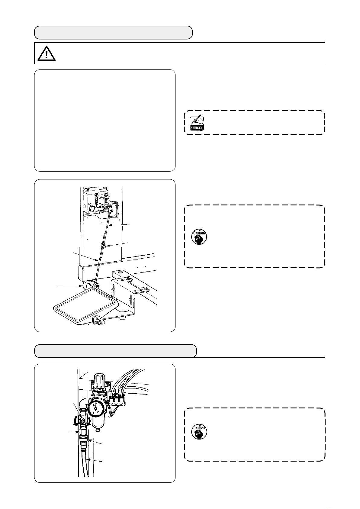
3. CONNECTING THE FOOT PEDAL
① Install the pedal base to the machine frame with
screws ❷.
②Connect pedal bases Aand Bwith two screws
❶.
Position of the pedal can be optionally
adjusted within the range of the slot.
③ Connect the connecting rods with xing screw
❸.
1. When connecting, do not connect the
rods with connecting rod Con the
sensor side pulled downward,
2. Install so that connecting rod on the
pedal side Dand the caster ❹do not
interfere with each other within the
range of pedal operation.
4. CONNECTING THE AIR COUPLER
Connect one end of air coupler Asupplied with
the machine as an accessory to air hose ❷. Then
connect the other end to coupler ❸on the main unit
side.
• Connect coupler A to the main unit
with air cock ❶ closed, then carefully
open air cock ❶to allow the com-
pressed air to be supplied.
• Make sure that the pressure gauge of
the regulator reads 0.5 MPa.
CAUTION :
When installing the pedal, perform the work paying attention to the overhead table.
❶
A
❸
❷
❶
❶
A
B
❷
❸
C
D
❹
− 6 −
5. CONNECTING THE POWER PLUG
Connection of the power plug to the power depends on the specications of the product. Adjust the power
plug to the power specications to connect.
① In case of the product of single-phase, 220 to 240V specications :
Connect the sky-blue and brown wires of the power cord to the power terminal (AC220 to 240V) and the
yellow/green wire to the ground (earth) terminal respectively.
② In case of the product of 3-phase, 200 to 240V specications :
Connect the red, white and black wires of the power cord to the power terminal (AC200 to 240V) and
the yellow/green wire to the ground (earth) terminal respectively.
③ In case of the product with the optional high voltage transformer (with SA-128) :
Connect the black wires (3 pieces) of the power cord to the power terminal (AC380 to 415V) and the
yellow/green wire to the ground (earth) terminal respectively.
It is possible to connect to 380/400/415V by setting of the input tap of transformer (standard setting at
the time of delivery : 380V).
CAUTION :
To prevent possible accidents caused by leakage or dielectric strength, an appropriate power plug
shall be installed by a person who has an expert knowledge of electricity. Be sure to connect the pow-
er plug to the receptacle that is well grounded.
This product performs operation by the single-phase connection for 3-phasse 380/400/415V.
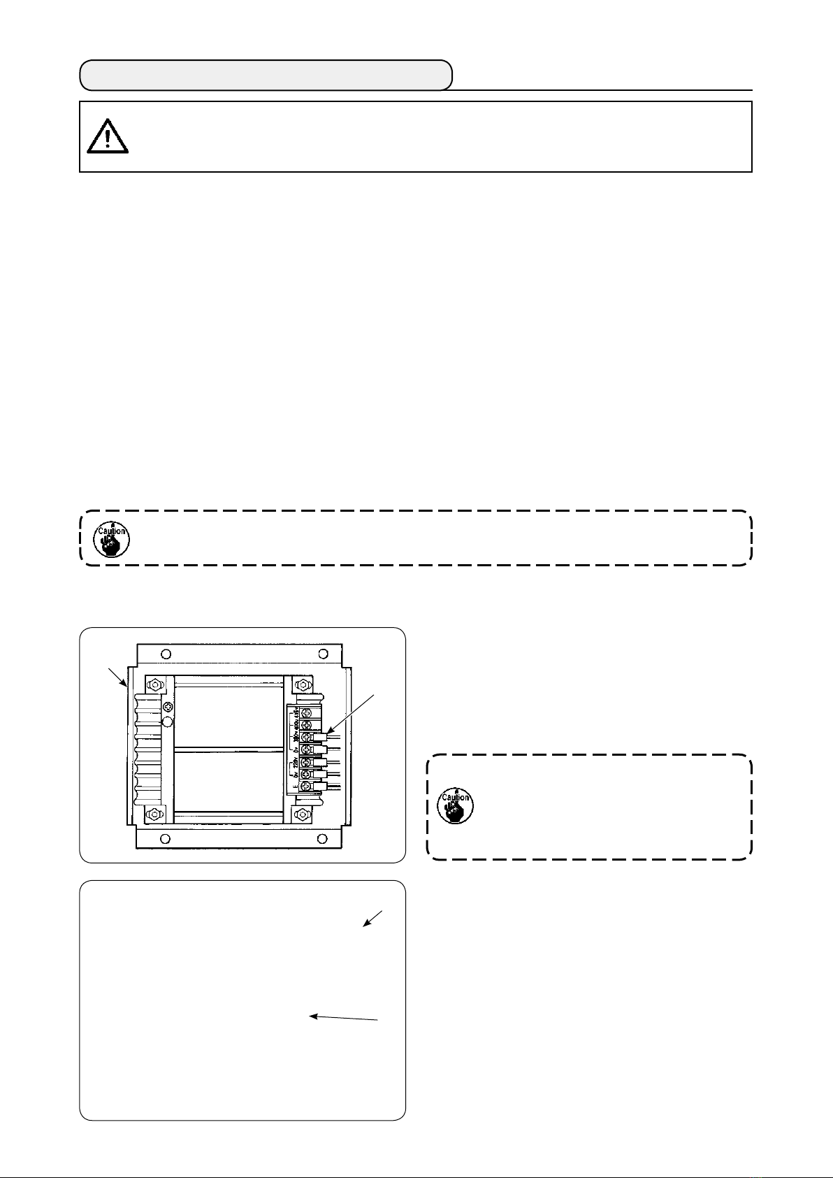
[ Caution when changing the power source of the high voltage optional transformer ]
When using high voltage optional transformer ❶with
the input voltage of 400V or 415V, it is necessary to
replace input power source cord ❷ of high voltage
optional transformer ❶. Change power source input
cord ❷ (sky blue) that is connected to 380V to the
connection of 400V or 415V.
To prevent accidents, perform the work
after leaving the sewing machine alone
more than 4 minutes in the state that
the power switch is turned OFF and the
power cord is drawn out.
High voltage optional transformer ❶is set on the
rear side of the table.
When performing changeover of voltage, remove
transformer box ❹ after removing top cover ❸.
❸
❹
❶
❷
Inhaltsverzeichnis
Andere SanDisk Nähmaschine Handbücher


