SeaLevel SeaLINK+4M.SC Bedienungsanleitung

1
© Sealevel Systems, Inc. 2433 Manual | SL9348 8/2021
SeaLINK+4M.SC
User Manual | 2433

2
© Sealevel Systems, Inc. 2433 Manual | SL9348 8/2021
Contents
CONTENTS............................................................................................................................................................................................................................2
INTRODUCTION...................................................................................................................................................................................................................3
BEFORE YOU GET STARTED..............................................................................................................................................................................................4
OPTIONAL ITEMS ................................................................................................................................................................................................................5
INSTALLATION & CONFIGURATION.................................................................................................................................................................................7
HARDWARE INSTALLATION..............................................................................................................................................................................................8
VERIFYING INSTALLATION................................................................................................................................................................................................9
HARDWARE CONFIGURATION.......................................................................................................................................................................................10
HARDWARE DESCRIPTION .............................................................................................................................................................................................14
SEALATCH™ USB .............................................................................................................................................................................................................16
SEALATCH LOCKING USB CABLES ................................................................................................................................................................................17
ELECTRICAL SPECIFICATIONS .......................................................................................................................................................................................18
SILK SCREEN - 2433........................................................................................................................................................................................................20
TECHNICAL SPECIFICATIONS.........................................................................................................................................................................................21
APPENDIX A –TROUBLESHOOTING.............................................................................................................................................................................22
APPENDIX B –HOW TO GET ASSISTANCE..................................................................................................................................................................25
APPENDIX C –ELECTRICAL INTERFACE......................................................................................................................................................................26
APPENDIX D –ASYNCHRONOUS COMMUNICATIONS.............................................................................................................................................28
APPENDIX E –SILK-SCREEN - 2433............................................................................................................................................................................29
APPENDIX F –COMPLIANCE NOTICES.........................................................................................................................................................................31
WARRANTY ........................................................................................................................................................................................................................32

3
© Sealevel Systems, Inc. 2433 Manual | SL9348 8/2021
Introduction
Overview
The Sealevel’s SeaLINK 2433 USB to serial interface adapter provides RS-232, RS-422, or RS-485 serial
ports via USB and is ideal for rugged and industrial environments. All configuration and electrical interface
selections are handled through the driver and each port is individually software configurable for RS-232,
RS-422, or RS-485 (full and half duplex).
Sealevel’s SeaCOM USB software drivers and utilities package makes installation and operation easy for
Windows 98, ME, 2000, XP, and Vista operating systems. Once the software is installed, plug the 2433 into
an available USB port and each serial port is recognized as a standard COM port by the host system
enabling compatibility with legacy software. The devices maintain their electrical interface settings locally,
allowing the host computer to be repaired or upgraded without reconfiguring the serial ports. Additionally,
the devices can be configured at one computer and deployed to other computers.
Two convenient USB 1.1 hub ports are included on the front of the enclosure for easily connecting
additional SeaLINK devices or standard USB peripherals. The 2433 integrates three SeaLATCH USB ports,
which are fully compatible with standard USB cables. The metal thumbscrew on the included USB cable
with a SeaLATCH USB type B connector provides a secure connection and prevents accidental cable
disconnection. Additionally, the highly retentive type B connector helps prevent unintentional separation
from a standard USB cable.
Standard operating temperature range is 0°C to 70°C and extended temperature range (-40°C to +85°C) is
optional. Status LEDs display electrical interface selection and serial data activity for each port.
Features
•Each port is individually software configurable for RS-232, RS-422, and two-wire or
four-wire RS-485
•Electrical interface settings maintained across multiple computers
•High speed UART with 128-byte Tx FIFO and 384-byte Rx FIFO
•+5VDC input power passed through on pin 9 of each DB9M connector and fused at
500mA for powering serial peripherals
•Includes two powered, fully rated (500mA) USB 1.1 downstream hub ports
•Automatic hardware RS-485 enable/disable
•Each serial port supports data rates to 921.6K bps
•Four DB9M connectors
•Status LEDs indicate power, electrical interface, and serial data activity for each port

4
© Sealevel Systems, Inc. 2433 Manual | SL9348 8/2021
Before You Get Started
What’s Included
The SeaLINK 2433 USB is shipped with the following items. If any of these items is missing or damaged,
contact the supplier.
•SeaLINK+2433 USB to RS-232/422/485 Four Port Serial Interface Adapter
•CA356 –USB Type A to SeaLATCH USB Type B Device Cable, 6’ in Length
•TR124 –Wall-mount AC power supply (5VDC @ 4A), locking DC connector
Advisory Conventions
Warning
The highest level of importance used to stress a condition where damage could result to the
product, or the user could suffer serious injury.
Important
The middle level of importance used to highlight information that might not seem obvious or a
situation that could cause the product to fail.
Note
The lowest level of importance used to provide background information, additional tips, or other
non-critical facts that will not affect the use of the product.

5
© Sealevel Systems, Inc. 2433 Manual | SL9348 8/2021
Optional Items
Depending upon your application, you are likely to find one or more of the following items useful with the
2433. All items can be purchased from our website (http://www.sealevel.com) or by calling our sales
team at 864-843-4343.
Cables
DB9F to DB25M (RS-232) Extension Cable
(Item# CA177)
The CA177 is a standard AT-style RS-232 modem cable
with a DB9F connector on one end and a DB25M
connector on the other. This cable is 72 inches in length.
DB9F to DB9M Extension Cable
(Item# CA127)
The CA127 allows users to extend a DB9 cable up to six
feet. The connectors are pinned one-to-one so the cable
is compatible with any device or cable that has DB9
connectors.
DB9F (RS-422) to DB25M (RS-530) Cable
(Item# CA176)
The CA176 allows users to convert any Sealevel RS-422
DB9 Male asynchronous adapter to an RS-530 DB25
Male pinout. This cable is ten inches in length.

6
© Sealevel Systems, Inc. 2433 Manual | SL9348 8/2021
Optional Items, Continued
Terminal Blocks
Terminal Block –DB9F to 9 Screw Terminals
(Item# TB05)
The TB05 terminal block breaks out a DB9 connector to
nine screw terminals to simplify field wiring of serial
connections including RS-422 and RS-485 networks. The
TB05 is designed to connect directly to Sealevel DB9
serial cards or any cable with a DB9M connector.
Terminal Block –Dual DB9F to 18 Screw Terminals
(Item# TB06)
The TB06 terminal block breaks out dual DB9
connectors to 18 screw terminals to simplify field wiring
of serial connections including RS-422 and RS-485
networks. The TB06 is designed to connect directly to
Sealevel dual port DB9 serial cards or any cable with
DB9M connectors.
Adapters and Converters
DB9F to RJ45 Modular Adapter
(Item# RJ9S8)
The RJ9S8 is a DB9 female to RJ45 adapter. It can be
configured without tools, and it is an excellent choice for
using available infrastructure wiring.

7
© Sealevel Systems, Inc. 2433 Manual | SL9348 8/2021
Installation & Configuration
Software Installation
Windows 98/ME/2000/XP/Vista™ Operating Systems
1. Begin by locating, selecting, and installing the correct software from the Sealevel software driver
database.
2. Select the Part Number (2433) for your device from the listing.
3. Click the ‘Install Drivers’ button.
4. The setup file will automatically detect the operating environment and install the proper
components.
To confirm that the SeaCOM driver has been successfully installed, click on the ‘Start’ button, and
then select ‘All Programs’. You should see the ‘SeaCOM’ program folder listed.
You are now ready to proceed with connecting the 2433 to your system. Refer to the Hardware
Installation section for details.
Windows NT is not USB aware and thus cannot support this
device.

8
© Sealevel Systems, Inc. 2433 Manual | SL9348 8/2021
Hardware Installation
Do not connect the device to a USB port on your motherboard until the software has been
successfully installed.
To install the 2433, first power the device using the included wall-mount power supply. Next, plug the device
into an available USB port using the supplied USB cable. Once both the power and USB connections are
secure the green power LED will light. The following instructions were tested with Windows XP and may
vary based on your version of Windows.
Once the device has been connected, the Found New Hardware wizard will appear first for the root hub and
then for each port that you are installing. Follow the instructions on the following page to finish installation.
The installation will repeat twice for each COM port (a total of 4 times on two port devices). This is
a limitation in the way Windows installs USB serial devices.
1. Click on ‘Install the software automatically’ followed by the ‘Next’ button.
2. Windows will show a warning message that the hardware has not passed
Windows logo testing. Click on ‘Continue Anyway’.
3. Click on ‘Finish’. Repeat this process for the remaining ports on the 2433.
All applications and drivers have been fully tested to maintain the integrity of your operating
system. Clicking on ‘Continue anyway’ will not harm your system in any way.

9
© Sealevel Systems, Inc. 2433 Manual | SL9348 8/2021
Verifying Installation
To confirm that the serial ports have been successfully installed, look in Device Manager under ‘Ports (COM
& LPT)’. The COM assignments will be included with the associated COM numbers in parentheses.
To access Device Manager in Windows 10:
1. Right-click on the Start button (Windows logo).
2. In the fly-out menu, click ‘Device Manager’.
3. Continue with step 4 below.
To access Device Manager in Windows 7:
1. Right-click on ‘Computer’ in the Start menu.
2. Click ‘Manage’ in the fly-out menu to launch the ‘Computer Management’ console window.
3. In the left pane under ‘System Tools’, click ‘Device Manager’.
4. In right pane near the bottom, expand the ‘Ports (COM & LPT)’ section by clicking the ‘>’ symbol.
5. You should now see the COM assignments with the associated COM numbers in parentheses.
Your system will assign the next available COM numbers, which will vary by computer (COM 6-7
as shown in this example).
10
© Sealevel Systems, Inc. 2433 Manual | SL9348 8/2021
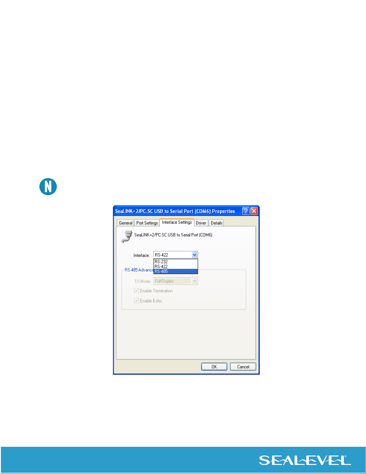
Hardware Configuration
Electrical Interface Mode Selection
The SeaLINK 2433 offers RS-232, RS-422, and RS-485 (full and half duplex) modes. The electrical interface
is a software selectable feature that can be accessed and changed using the Sealevel SeaCOM driver via
Device Manager. To select the electrical interface, follow the steps below:
1. Open Device Manager and locate ‘Ports (COM&LPT)’ following the steps above. You
should see each of the 2433’s ports listed.
2. Select one of the ports by right-clicking on it and selecting ‘Properties’ from the fly
out menu. The serial port properties menu will appear
3. Click on the ‘Interface Settings’ tab
The Sealevel SeaCOM driver adds the ‘Interface Settings’ tab. If this tab is missing, SeaCOM is not
correctly installed.
4. Select the appropriate electrical interface for your application and click on ‘OK’.
Dieses Handbuch passt für folgende Modelle
1
Inhaltsverzeichnis
Andere SeaLevel Netzwerk-Hardware Handbücher


Beliebte Netzwerk-Hardware Handbücher anderer Marken

Matrix Switch Corporation
Matrix Switch Corporation MSC-HD161DEL Bedienungsanleitung

B&B Electronics
B&B Electronics ZXT9-IO-222R2 Bedienungsanleitung

Yudor
Yudor YDS-16 Bedienungsanleitung

D-Link
D-Link ShareCenter DNS-320L Bedienungsanleitung

Samsung
Samsung ES1642dc Gebrauchsanweisung

Honeywell Home
Honeywell Home LTEM-PV Montageanleitung


