- 3 - - 4 -
- 5 - - 6 -
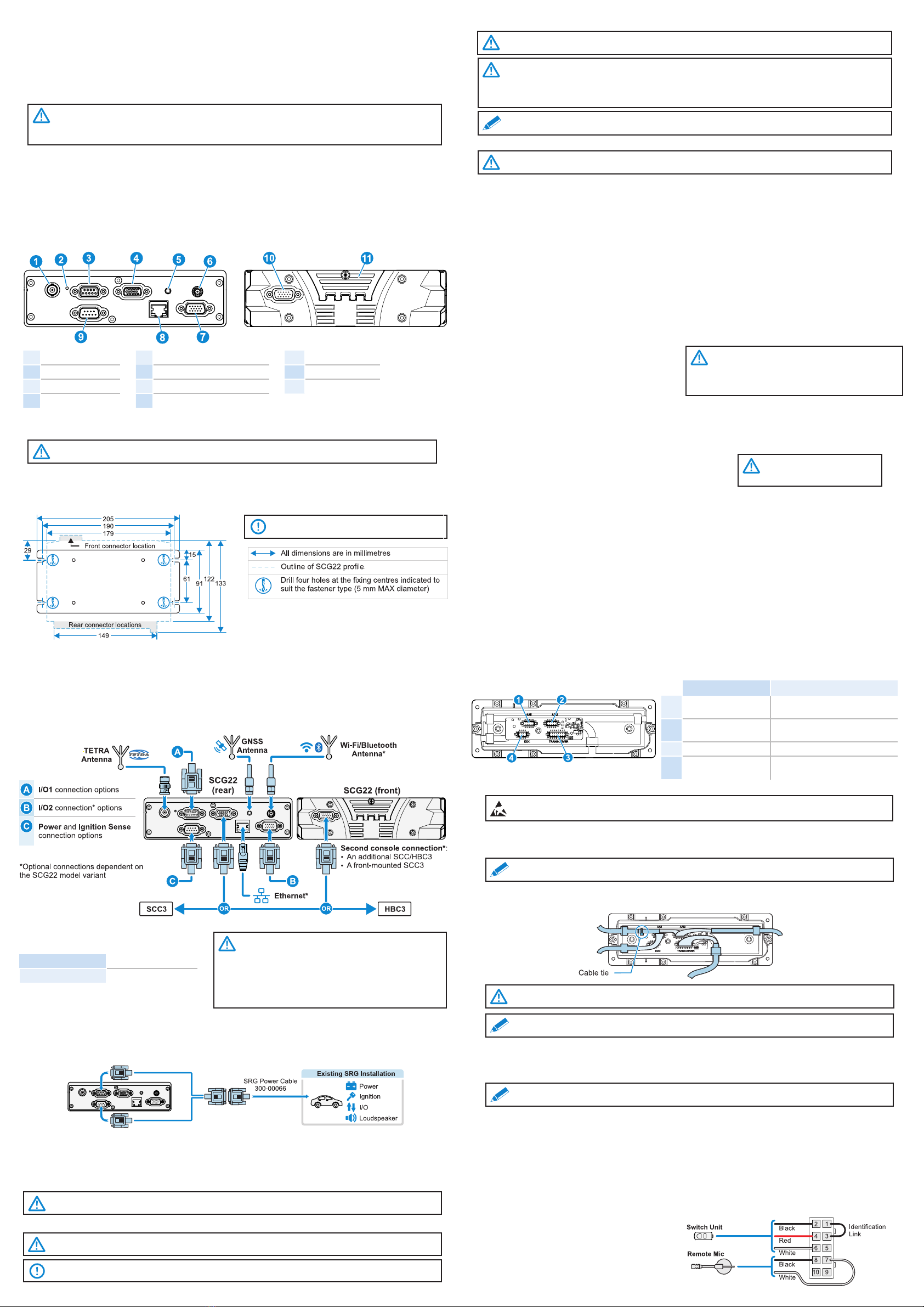
SCG22 Components and Connections
Rear Panel Front Panel
1TETRA Antenna
2LED Indicator
3I/O1/SPK1/PRG
4Console 1
5GNSS Antenna
6Bluetooth & Wi-Fi Antenna*
7I/O2/SPK2*
8Ethernet*
9Power
10 Console 2*
11 SIM Card Cover
*Optional connections depending on the model
variant.
Mounting Bracket
If the SCG22 needs to be installed on a at surface, such as in a car boot, the xed mounting bracket option supplied (in the
box) can be used. Fit the mounting plate to the bottom of the SCG22 using the four screws supplied. Secure the mounting
bracket and SCG22 assembly to the desired surface using four screws. The bracket can be used as a template to mark and
pre-drill the holes if required.
CAUTION! Ensure xing screws are of an appropriate type and length for the surface material the bracket is
being mounted on to.
IMPORTANT! Allow sucient space around the
SCG22 for cables and access to connectors.
SCG22 Cabling and Connections
Loudspeaker Connections
The following lead options provide connection to
loudspeakers:
• SCG Loudspeaker / IO Lead
• SCG Loudspeaker / IO USB Host Lead
• SCG Expansion Board Loudspeaker / 8 GPIO Lead
DC Supply Connection
The following lead options provide connection to the DC supply:
• SCG Power / Ignition Lead
• SCG Power / Ign / IO Adapter Lead
It is recommended that the power cable runs are kept as short as possible. In a new installation where the SCG Power / Ignition
Lead is used:
1. With the SCG22 end of the power connector resting in its intended nal position, route the wires to the vehicle battery,
threading the cable through the bulkheads if necessary (include the blue wire where ignition switching is not required, see 3
below).
WARNING! 12V supply leads, antenna cables and speaker wiring must be routed as far away as possible
from gas or fuel lines, and any in-vehicle electrical wiring. This reduces the risk to safety in the event of a leak.
CAUTION! Ensure that the cables are routed so that they are kept clear of any existing vehicle system
cabling. Ensure that the colour console cable and any loudspeaker cables are routed so that they are kept
well clear of antenna cables and of any other electronic devices such as electromagnetic systems or AM/FM
radios. Secure all cabling to eliminate the possibility of damage by sharp edges or moving parts.
All cabling should be hidden and not left loose.
Note: Both the remote console and loudspeaker extension cables are colour coded blue at the SCG22 end to
aid installation before the SCG22 is installed.
CAUTION! The transceiver is designed for nominal 12V negative earth systems. DO NOT use on other supply
systems because this will result in damage to the product.
CAUTION! The transceiver will be damaged if either
of the loudspeaker conductors (grey twin conductor
cable) is connected to ground. If the loudspeaker
output is to be connected to other audio systems, an
audio isolation transformer must be used.
Digital I/O Connections
The following lead options provide programmable IO connection lines:
• SCG Power / Ign / IO Adapter Lead
• SCG Loudspeaker / IO Lead
USB Connections
A host* connection lead is available for connecting approved USB devices:
• SCG Loudspeaker / IO USB Host Lead
Ethernet Connection (optional)
The SCG Ethernet connector provides an additional connection for data.
CAUTION! *Do not exceed the
maximum current rating when
powering USB devices.
TETRA Antenna
For best all round performance of the product, the antenna should be tted on the centre of the vehicle roof. Alternative
positions, such as wing mounting, will give degraded performance. The coaxial feeder should be secured along its length to
eliminate the possibility of damage by sharp edges or moving parts.
GNSS Antenna Installation
The SCG22 can be licensed to activate the GNSS antenna socket. Please note that the transceiver tracks GLONASS and GPS
satellites simultaneously. See customer support bulletin CUS-14-2045.
The antenna unit connects to a SMC connector on the rear panel of the transceiver and should, ideally, be mounted on the
highest point of the vehicle (i.e., roof) with an uninterrupted view of the sky, and as far from the TETRA antenna as possible.
For mounting, follow the manufacturer’s installation instructions. It is recommended to t the GNSS antenna connector before
connecting the Remote Console Cable.
An active antenna is recommended, the supply of which is on the centre pin, 5 V nominal, 40 mA maximum. This supply feed is
short circuit protected.
Bluetooth/Wi-Fi Antenna Installation (optional)
If a Bluetooth/Wi-Fi receiver is tted at the time of manufacture, a Bluetooth/Wi-Fi antenna socket will be tted.
The antenna unit connects to a SMA connector on the rear panel of the transceiver and should, ideally, be mounted on the
highest point of the vehicle (i.e., roof), and as far from the TETRA antenna as possible. For mounting, follow the manufacturer’s
installation instructions. It is recommended to t the Bluetooth/Wi-Fi antenna connector before connecting the Remote Console
Cable.
Cabling and Connections Overview - All Models
Programmable I/O
The SCG22 supports the following programmable
digital I/O lines, depending on the variant:
GPIO 1 Connector Two I/O lines available
GPIO 2 Connector Eight I/O lines available
WARNING! To control devices from the programmable
outputs which require more than 0.5 A, use a suitable
automotive relay to ensure correct operation. Connect
the relay coil between the output wire and the vehicle
positive supply. The device must be protected by an
appropriate fuse in its positive supply. Check with the
local regulatory authority where the outputs are used to
drive external alert devices such as horns or sirens.
SCC3 Console
The SCG22 can accommodate up to two SCC3 consoles, or a combination of an SCC3 and an HBC3 handset-based console.
SCC3 Connections and Cabling
The SCC3 has four internal connectors that are used to provide connection to the transceiver and accessories as shown:
Connector Device
1AAI1 (Audio Accessory
Interface 1)
Remote Microphone and Switches
or Handset/Microphone
2AAI2 (Audio Accessory
Interface 2) Handset/Microphone
3TRANSCEIVER SCG22
4DDC (Dedicated Data
Connector) Mobile Data Terminal (MDT)
Cabling the SCC3
2. Route the cables through the channels on the internal moulding. Fit the split bung and the cable tie (supplied) around
the cables (as shown). Tighten the cable tie behind the bung to secure the cables and allow slack at the 10-way plug
termination.
1. Connect the colour console cable into the connector marked TRANSCEIVER on the SCC3. Press the strain relief grommet
into the recess in the channel. Connect the 16-way D-type connector to either the Console 1 connector on the rear panel, or
the optional Console 2 connector on the front panel of the SCG22.Connect all other accessories to the SCC3.
WARNING! Before starting to install the SCC3 console, see the section “Installation Precautions” on page 1.
WARNING! Ensure that the transceiver is powered OFF before making any connections to the SCC3.
IMPORTANT! If the SCC3 is mounted directly to the SCG22 the internal connectors are not accessible.
CAUTION! ESD precautions must be taken during replacement of the rear cover.
Note: If the SCC3 is being tted with the DIN Mount Kit, refer to the full installation guide for details on
routing and securing the cables.
CAUTION! Cables must be routed correctly using the channels to prevent damage. Press the cable bung
into the recess in the channel. Fit the bungs provided into any unused channels.
Note: If a handset or st-microphone accessory is used, the hands free kit must be plugged into the Audio
Accessory Interface 1 connector (back left) to allow all cables to be routed correctly.
Fist Microphone/Handset
The Fist microphone and/or Handset should be located centrally for the operator(s) to access, using the screws provided.
Ensure that the cables are placed in the rear of the SCC3 so that the grommets seal correctly. Specic accessories attach to
the Vehicle Accessory Connector (VAC). These should be used when mounting in a DIN slot.
Multiple Fist Microphones and/or Handsets may be connected in an installation, which may be connected to either audio
accessory interface.
Note: If replacing a rear connecting handset with a front connecting handset, also replace the magnetic hook
rest with the one supplied.
Remote Microphone and Switches Installation
It is recommended that the microphone is located away from any wind noise in a position suitable for the user, such as near the
internal rear view mirror.
The switch unit should also be located centrally for the user to access. A self-adhesive hook and loop pad is provided for
mounting the remote PTT on a at surface, such as the dashboard.
Only one hands free microphone can be used in an installation, which can be connected to either audio accessory interface
socket on the rear panel of the SCC3.
See the section “SCC3 Connections and Cabling” on page 5.
2. The positive power line must include a fuse as close as possible to the power source. The negative power line must be
connected close to the battery-to-vehicle-body connection (not directly to the battery) and must not include a fuse.
3. The blue wire provides an ignition sensing input. If ignition switching is required, trim the wire to length so that it can be
wired, via a fuse, to the ignition switch, using the splicing connector provided. Otherwise this wire must be connected, via a
fuse, to the permanent positive supply. A fuse must always be tted close to where the wire is connected.
4. Check the installation and t the blade fuses. Fuse rating:
• Positive supply 10A, Ignition sense 1A (Automotive 19 mm blade type - Littelfuse ATO®).
• SCG Loudspeaker / IO USB Host Lead
• SCG Expansion Board Loudspeaker / 8 GPIO Lead
RF Compatibility Checks
On completion of the installation, the following checks must be carried out if the vehicle is equipped with electronic
anti-skid, electronic ignition or engine management systems.
WARNING! In the event of an apparent malfunction in the braking or any other systems during RF
compatibility checks, the SCG22 installation should be rendered inoperative and the vehicle manufacturer
should be contacted before any further use is made of the SCG22 installation. Unqualied persons should not
attempt to modify these units in any way.
The transmitter should be operated only for the time required to make an observation. Ideally these checks should be
performed on the TETRA system. If this is not possible, perform the checks in DMO.
An assistant will be required for the following checks:
1. With the vehicle stationary and the engine running at fast idle, operate the transmitter. Check that the brake lights do not
illuminate and that the engine continues to run normally, i.e., with no surging or cutting out.
2. Operate the brake pedal, key the transmitter and check that the brake lights do not extinguish.
3. Put the vehicle into motion at a speed of 15 – 25 km/h (10 –15 mph), key the transmitter and operate the brake pedal
simultaneously. Check that the braking action is normal and that the engine does not surge or cut out.
Ensure that the installation does not impede the normal operation of the vehicle, including the operation of any safety devices
such as airbags and seatbelt retainers.
The SCG22 should be positioned so that it does not obstruct, or become at risk of damage from, any occupant or carried items.
Ensure sucient space is provided above the installation to allow tment and removal of the SCG22.
Protect the rear panel connectors and connecting cables from the risk of impact damage. If a connector is not in use, the dust
covers or seal bungs provided must be tted to reduce the risk of damage or dust/moisture ingress.
Cabling and Connections to an SRG Installation
If the vehicle was previously tted with an SRG mobile radio installation, the SCG22 can be connected to the existing SRG
power cable using one of the optional adapter cables available. Existing ignition, IO and loudspeaker functions from the current
installation will be retained.
SCG Power / Ign / IO Adapter Lead (300-02007)
SRG I/O Compatibility
Only two of the existing SRG I/O lines are connected through the adapter lead and available for use with the SCG22.
The I/O lines must be congured on the SCG22 so that I/O0 is an output and I/O1 is an input.
Connector Wiring Terminations
The remote microphone is supplied unterminated for
ease of installation. Terminate to the SCC3 as shown
after the switch unit and microphone are positioned.



