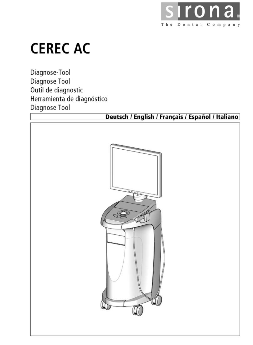
Sirona cerec ac Bedienungsanleitung

MSKOMNN
`bob`=^`
kÉï=~ë=çÑW==
båÖäáëÜ
aá~ÖåçëíáÅ=qççä

63 24 599 D3492
2D3492.076.03.02.02 06.2011
Sirona Dental Systems GmbH
Table of contents Diagnostic Tool CEREC AC
Table of contents
1Components of the CEREC AC diagnostic tool ....................................................... 3
2Localizing faults........................................................................................................ 4
3Power supply test..................................................................................................... 5
4Camera test.............................................................................................................. 6
4.1 Monitor power supply .................................................................................... 6
4.2 Bluecam ........................................................................................................ 6
4.3 Camera cable................................................................................................ 7
5PC diagnostic tool .................................................................................................... 8
5.1 Starting the diagnostic tool............................................................................ 8
5.2 Test procedure .............................................................................................. 9
5.2.1 Customer Diagnostics........................................................................ 9
5.2.2 Technician Diagnostics ...................................................................... 11
5.2.3 Sirona Windows Diagnostics.............................................................. 13
5.3 Rebooting the PC.......................................................................................... 14
5.4 Troubleshooting ............................................................................................ 14
5.4.1 Customer Diagnostics........................................................................ 15
5.4.2 Technician Diagnostics ...................................................................... 17
5.4.3 Sirona Windows Diagnostics.............................................................. 19
6Updating the BIOS setting........................................................................................ 20
6.1 Determining the BIOS version....................................................................... 23
6.2 Determining the hardware version of the unit ............................................... 23

63 24 599 D3492
D3492.076.03.02.02 06.2011 3
Sirona Dental Systems GmbH Components of the CEREC AC diagnostic tool
Diagnostic Tool CEREC AC
båÖäáëÜ
1Components of the CEREC AC diagnostic
tool
● Voltage tester for the PC power supply (Lindy)
● Power button cable for switching on the PC
● Power cable extension for the PC power supply
● Monitor cable (L6)
● PC test tool (software CD)
● Restore CD with BIOS update and BIOS settings
● Camera tester
● Replacement camera cable
● Instructions for PC and camera diagnosis

63 24 599 D3492
4D3492.076.03.02.02 06.2011
Localizing faults Sirona Dental Systems GmbH
Diagnostic Tool CEREC AC
2Localizing faults
Perform power supply test Power supply test [ ➙ 5]
Supply power to monitor via camera
tester
Camera test [ ➙ 6]
Check camera and camera cable
with the camera tester
Use PC test tool PC diagnostic tool [ ➙ 8]

63 24 599 D3492
D3492.076.03.02.02 06.2011 5
Sirona Dental Systems GmbH Power supply test
Diagnostic Tool CEREC AC
båÖäáëÜ
3Power supply test
The CEREC AC diagnostic tool contains an "ATX power supply tester"
manufactured by "Lindy".
Preparing for the test
✔The PC is switched off.
✔The main switch of the CEREC AC is switched off.
1. Remove the PC from the CEREC AC and open it.
2. Connect the cables of the PC power supply to the ATX power supply
tester as described in the attached user manual.
3. Plug the attached power extension cable into the power cable of the
CEREC AC and into the PC.
ªThe PC is supplied with the necessary supply voltage of 230
VAC.
4. Plug the power button cable into the PC
ªThe PC can be switched on without connecting a keyboard. The
green lamp in the button indicates whether the 5V standby volta-
ge is present in the PC.
5. Switch the CEREC AC on at the main switch.
6. Switch the PC on at the power button cable.
Test procedure
➢The application of the tester is described in the attached user manual
of the ATX power supply tester. The user manual is available in Eng-
lish, German, French and Italian.
A defective power supply is detec-
ted
No defective power supply is de-
tected
The power supply is defective. Re-
place the power supply with a new
one.
The power supply is not defective.
Plug all cables of the power supply
back into the PC.
Important: Make sure that all cab-
les are plugged back in to the posi-
tions where they were originally
located before the test.

63 24 599 D3492
6D3492.076.03.02.02 06.2011
Camera test Sirona Dental Systems GmbH
Monitor power supply Diagnostic Tool CEREC AC
4Camera test
Using the camera tester, you can check the monitor power supply, the
Bluecam and the camera cable.
Preparing for the test
✔The PC is switched off.
1. Unscrew the rear cover of the CEREC AC.
2. Unplug the S-ATA cable for the DVD drive.
3. Plug the S-ATA power supply cable into the S-ATA interface of the
PC where the DVD drive was previously connected.
4. Connect the USB cable to a free USB port of the PC.
5. Switch the PC on and wait until it has finished booting up.
4.1 Monitor power supply
✔The 12 VDC required for the power supply of the LCD monitor of the
CEREC AC are available at the 4-pole socket of the camera tester.
1. Unplug the power supply cable from the socket of the PC-internal po-
wer supply board.
2. Plug it into the corresponding socket of the camera tester.
4.2 Bluecam
1. Unscrew the Bluecam cable from the PC.
2. Plug it into the socket of the camera tester.
3. Open the CEREC application and take an exposure with the camera.
The monitor shows no function
Replace the monitor (replacement LCD monitor 62 35 951).
No camera image is displayed A camera image is displayed
Go on to the next test step. The supply board in the PC is de-
fective. Replace the supply board
in the PC (replacement supply
board 61 37 421).

63 24 599 D3492
D3492.076.03.02.02 06.2011 7
Sirona Dental Systems GmbH Camera test
Diagnostic Tool CEREC AC Camera cable
båÖäáëÜ
4.3 Camera cable
1. Connect the replacement camera cable to the Bluecam camera and
the camera tester.
2. Open the CEREC application and take an exposure with the camera.
No camera image is displayed A camera image is displayed
The Bluecam camera is defective.
Replace the Bluecam camera
(Bluecam rep. 62 36 884 or Blue-
cam replacement 62 36 694).
The camera cable was the cause of
the fault. Replace the camera cab-
le with the one attached to the CE-
REC AC diagnosis tool.
Tip: Replace the camera cable re-
moved from the CEREC AC dia-
gnosis tool with a new replacement
camera cable (replacement Blue-
cam camera cable 62 35 845).

63 24 599 D3492
8D3492.076.03.02.02 06.2011
PC diagnostic tool Sirona Dental Systems GmbH
Starting the diagnostic tool Diagnostic Tool CEREC AC
5PC diagnostic tool
5.1 Starting the diagnostic tool
Tip: If one of the following steps doesn't work, look for the following steps
in the service manual.
✔The PC is switched off.
1. Switch the PC on and wait until the message shown above appears.
2. Press and hold "F11" on the keyboard until the boot menu appears.
Test Suitable for
Customer Diagnostics Suitable for the user when checking the
PC components.
Technician Diagnostics Suitable for the technician or service
engineer when checking the PC com-
ponents.
Sirona Windows Diagnostics Windows stress test to check the PC
under continuous load.

63 24 599 D3492
D3492.076.03.02.02 06.2011 9
Sirona Dental Systems GmbH PC diagnostic tool
Diagnostic Tool CEREC AC Test procedure
båÖäáëÜ
3. Insert the diagnostic tool CD in the drive and select "CD/DVD:…" in
the menu using the arrow keys.
ªThe PC boots from the CD.
4. Wait until the light on the drive goes out.
5. Confirm your selection by pressing the "Return" key on the key-
board.
ªThe diagnostic tool starts and a selection menu appears.
Tip: The "Customer Diagnostics" will start automatically af-
ter one minute if you did not press an arrow key beforehand.
6. Select the test with the arrow keys.
7. Confirm your selection by pressing the "Return" key on the key-
board.
ªThe test starts.
5.2 Test procedure
5.2.1 Customer Diagnostics
✔You have started the "Customer Diagnostics" test and the sys-
tem configuration is displayed.

63 24 599 D3492
10 D3492.076.03.02.02 06.2011
PC diagnostic tool Sirona Dental Systems GmbH
Test procedure Diagnostic Tool CEREC AC
1. Check the information in the system configuration to determine whe-
ther the system corresponds to the default settings. You can scroll up
and down using the arrow keys.
Tip: The test will start automatically in 3 minutes if you do not press
an arrow key first.
2. Press the "Esc" key on the keyboard.
ªThe test starts. The entire test run takes approx. 20 minutes.
ªThe result, i.e. "Pass" or "Fail" appears at the end of the test
(see sections entitled "Test result: "Pass" or "Test result: "Fail").
3. On completion of the test, press any key to go on to the test dialog.
Tip: You can scroll to the individual test steps using the arrow keys.
The corresponding result is shown in front of each test step.
4. To quit the test, reboot the PC (see Rebooting the PC [ ➙ 14]).
Andere Handbücher für cerec ac
9
Inhaltsverzeichnis
Andere Sirona Diagnosegeräte Handbücher