Smart temp Apollo Bedienungsanleitung
Installation Manual
Version 1.0
Smart Temp
Apollo
P/n 44-800

TABLE OF CONTENTS
Introduction .........................................................................................................6
Getting started ....................................................................................................7
Installing the thermostat ....................................................................................8
Disassembly ...........................................................................................8
Thermostat location ...............................................................................8
Mounting the subbase .........................................................................8, 9
Terminal designations ..........................................................................10
Installing the batteries ......................................................................................11
Setting the system switches .....................................................................12, 13
1

System switch functions ...................................................................13
Typical wiring diagrams ...............................................................14-24
Heat Only (Gas)......................................................................14
Heat Only (Electric).................................................................15
Cool Only.................................................................................16
2 or 3 Cool ...............................................................................17
1 Heat / 1 Cool .......................................................................18
2 Heat / 1 Cool........................................................................19
1 Heat / 2 Cool........................................................................20
1 Heat / 1 Cool Heat Pump.....................................................21
2 Heat / 1 Cool Heat Pump.....................................................22
2 Heat / 2 Cool Heat Pump.....................................................23
2 Wire - Gas Heating...............................................................24
TABLE OF CONTENTS
2

Installer setup menu ...................................................................................25-46
Entering the menu ...............................................................................25
Selecting programmable or non-programmable operation ..................26
Selecting program days (programmable mode)...................................27
Selecting programmable fan option.....................................................28
Selecting mode of operation................................................................29
Touchscreen lock options.....................................................................30
Selecting the cooling setpoint limit.......................................................31
Selecting the heating sepoint limit........................................................32
Selecting the temperature display.........................................................33
Selecting time format............................................................................34
Selecting setpoint display option..........................................................35
Selecting back light option...................................................................36
TABLE OF CONTENTS
3

Installer setup menu (Continued)
Selecting Adaptive Recovery................................................................37
Filter reminder......................................................................................38
Selecting the heating and cooling differential.......................................39
Internal sensor calibration....................................................................40
Remote sensor options........................................................................41
Assigning the ‘A’ relay..........................................................................42
Selecting low balance point.................................................................43
Selecting high balance point................................................................44
Audible beep option.............................................................................45
Factory reset........................................................................................46
Remote sensor installation.........................................................................47-51
Remote sensors..................................................................................................47
TABLE OF CONTENTS
4

Remote sensor installation (Continued)
Indoor sensor wiring ....................................................................................47-48
Using multiple sensors for temperature averaging.............................................49
Outdoor sensor wiring...................................................................................50-51
Temperature sensor calibration chart.................................................................51
Testing .........................................................................................................52-55
Testing fan operation...........................................................................................52
Testing conventional heating and cooling operation.....................................52-53
Testing conventional heat pump operation........................................................53
Testing fossil fuel operation...........................................................................53-54
Testing low balance point (heat pump or fossil fuel)...........................................54
Testing high balance point (heat pump or fossil fuel).........................................55
Adaptive recovery ............................................................................................55
Basic troubleshooting ................................................................................56-58
Specifications ...................................................................................................59
TABLE OF CONTENTS
5

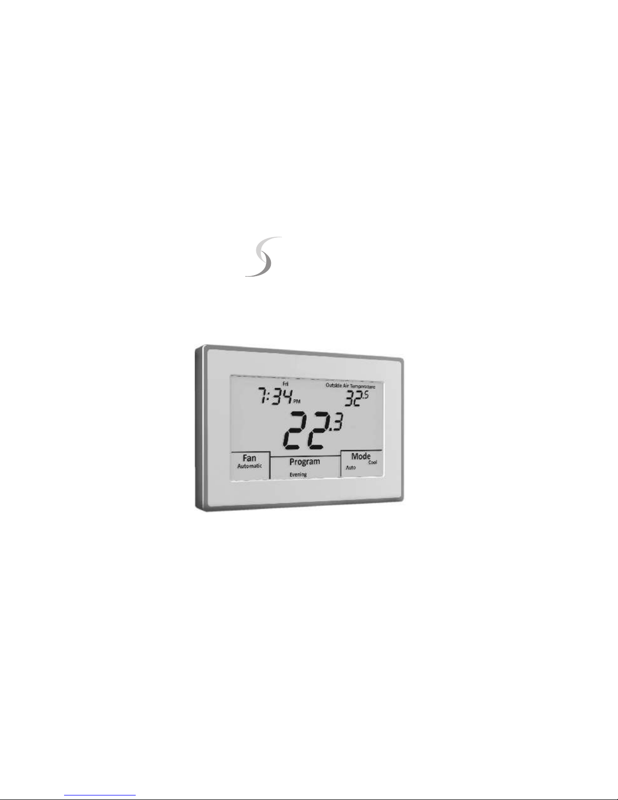
The Smart Temp 44-800 “Apollo” is a feature-rich touchscreen thermostat that can
be battery powered or hardwired to the HVAC equipment. Using a common sense
approach to the installation will ensure this product is installed properly and to the
customer’s satisfaction. Please take time to read and understand this manual so
that installation and testing is performed in an efficient manner.
This manual is to be used in conjunction with the supplied User Manual.
Although great care has been taken in the preparation of this manual, Smart
Temp Aust P/L takes no responsibility for errors or omissions contained
herein. It is the responsibility of the installer to ensure that this thermostat
and the equipment connected to it operate in a safe and efficient manner.
Due to ongoing product improvements, Smart Temp reserves the right to change the
specifications of the 44-800 thermostat or its components without notice.
All rights reserved.
© Smart Temp Australia P/L.
Intellectual rights apply.
INTRODUCTION
6

As with any HVAC project, careful installation is the key to a successful outcome.
Time taken during the installation process will be rewarded with fewer call-backs.
The steps required to install the 44-800 thermostat are as follows:
1. Read and understand this Installation Manual and Thermostat User Manual.
2. Mount and wire the subbase
3. Install the batteries
4. Set the 4 system switches to match the equipment application.
5. Wire optional remote temperature sensor(s).
6. Power the thermostat.
7. Set theAdvanced Installer settings.
8. Test the thermostat.
GETTING STARTED
7

DISASSEMBLY
There are two release slots located on the bottom of the thermostat. Gently push the flat blade
of a small screwdriver into one slot at a time and pry upward until the catch disengages.
Carefully swing the thermostat upward and away from the subbase. (Figure 1)
THERMOSTAT LOCATION
The 44-800 should be installed in a location that
represents the ambient space temperature. Do not
install the thermostat in an area where drafts are
present, near the floor, behind doors or on an external
wall. Avoid placing the thermostat in areas where the
air movement is limited, affected by direct sunlight or
other areas not typical of the temperature in the space.
MOUNTING THE SUBBASE
When mounting the 44-800 subbase, be aware that
drafts may travel down wall cavities and enter the back
of the thermostat through the control wire hole in
INSTALLING THE THERMOSTAT
FIGURE 1
8

the wall. It is important to seal the hole to prevent any drafts that might affect the internal
temperature sensor. Pull the control wires through the large opening in the thermostat
subbase. Next, level and mount the subbase on the wall using the supplied anchors and
screws. (Figure 2)
Do not over tighten the mounting screws as the subbase may warp causing the
improper seating of the thermostat
connecting pins to the terminal blocks.
Use a properly sized screwdriver and
back each screw terminal out (counter
clockwise) before landing each wire to its
dedicated terminal. Do not over tighten
the terminal screws.
Check to ensure that all wires are landed
correctly and dressed properly to prevent
any shorts.
Refer to Typical System Wiring Diagrams
in this manual for proper wiring. FIGURE 2
Out SC In A W Y G
Com
R
C
Smart Temp Aust P/L
www.thermostat.com.au
WIRE
ACCESS
HOLE
BATTERY
COMPARTMENT
MOUNTING HOLES
MOUNTING
HOLE
MOUNTING HOLES
INSTALLING THE THERMOSTAT
9
Dieses Handbuch passt für folgende Modelle
1
Inhaltsverzeichnis


