SmartCockpit Dash8 Bedienungsanleitung

12.5 (ATA 24) ELECTRICAL POWER
12.5.1 Introduction
The Electrical Power Generation and Distribution System (EPGDS) is used to supply the electri-
cal energy for all onboard electrical equipment. The EPGDS has DC and AC generating sys-
tems. The DC generation system includes a battery system. The EPGDS provides for energy
conversion, distribution, storage, control, protection, monitoring, and indication to the flight crew.
Provision is made for external connection of DC or AC external power while on the ground.
12.5.2 General
The DC generation system is supplied by three NiCad batteries, two engine driven starter/gener-
ators, two Transformer Rectifier Units (TRUs) and an optional Auxiliary Power Unit (APU). The
TRUs supply 28VDC and are powered by two engine driven Alternating Current (AC) generators
that supply 115Volts Alternating Current (VAC).
The power is distributed by an electrical bus system. It re configures for individual power source
and bus failures, by the automatic closing and opening of bus tie contactors.
There are both DC and AC external power receptacles for Ground Power Unit (GPU) connection.
All AC and DC aeroplane services can be operated from the AC generators or the AC external
power alone.
Dash8 - Q400 - Electrical
Page 1
12.5.3 Controls and Indications - Electrical Power
Dash8 - Q400 - Electrical
Page 2

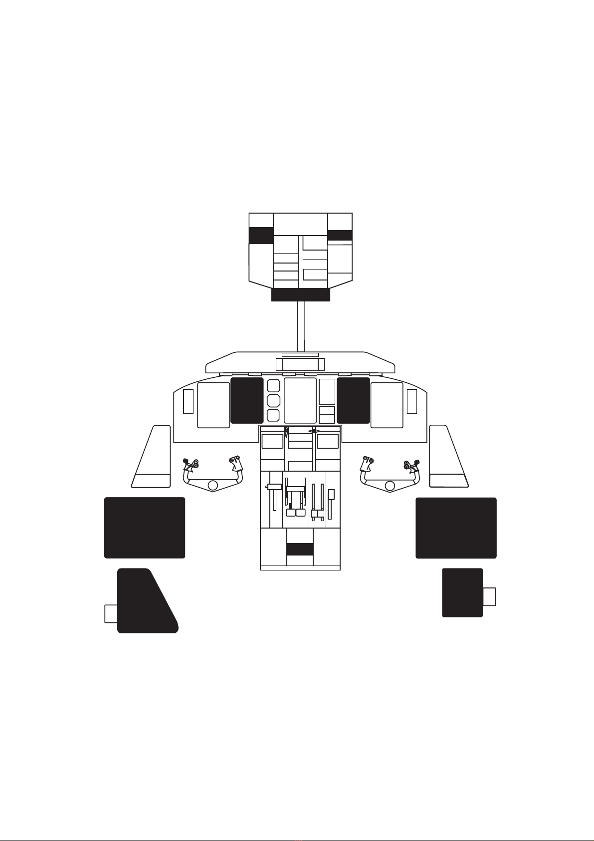
Figure 12.5-1 Engine and System Integrated Displays Control Panel (ESCP)
ESCP CALLOUTS PERTAINING TO ELECTRICAL ITEMS
1. ELEC SYS PUSHBUTTON (momentary action)
PUSH - provides a display of the electrical system page on the MFD (upper area) with MFD 1
or MFD 2 set at SYS
- there is no action with another push
ENG
SYS
NAV
PFD
MFD1
ENG
NAV SYS PFD
MFD2
ELEC
SYS
ENG
SYS
FUEL
SYS
DOORS
SYS ALL TEST
NORM
12
EFIS
ATT/HDG
SOURCE
ADC
OFF
ED BRT
NORM
12
SOURCE
EFIS
1
Dash8 - Q400 - Electrical
Page 3

Figure 12.5-2 DC Control Panel (1 of 3)
DC CONTROL
OFF
STBY
BATT
AUX
BATT
MAIN
BATT
BATTERY
MASTER
GEN 1 GEN 2 MAIN BUS
TIE
BUS FAULT
RESET
EXT PWR
OFF OFF OFF
OFF OFF OFF OFF OFF
12 3
Dash8 - Q400 - Electrical
Page 4

DC CONTROL PANEL CALLOUTS
1. STBY BATT switch (two position)
STBY BATT - left main feeder bus charging circuit connected to standby battery
- EPCU logic inhibits this connection under the following conditions:
• with external power (no charge) option
• when a DC bus fault is present on the left main feeder bus
• during emergency operations
OFF - disconnects standby battery from left main feeder bus
- STBY BATTERY caution light turns on any time the standby battery is not connected to
the left main feeder bus
2. AUX BATT SWITCH (two position)
AUX BATT - left main feeder bus charging circuit connected to auxiliary battery
- EPCU logic inhibits this connection under the following conditions:
• with external power (no charge) option
• when a DC bus fault is present on the left main feeder bus
• during emergency operations
OFF - disconnects auxiliary battery from left main feeder bus
- AUX BATTERY caution light turns on any time the auxiliary battery is not connected to
the left main feeder bus
3. MAIN BATT SWITCH (two position)
MAIN BATT - right main feeder bus charging circuit connected to main battery
- EPCU logic inhibits this connection under the following conditions:
• with external power (no charge) option
• when a DC bus fault is present on the right main feeder bus
• during emergency operations
OFF - disconnects main battery from right main feeder bus
- MAIN BATTERY caution light turns on any time the main battery is not connected to the
right main feeder bus
Dash8 - Q400 - Electrical
Page 5

Figure 12.5-3 DC Control Panel (2 of 3)
DC CONTROL
OFF
STBY
BATT
AUX
BATT
MAIN
BATT
BATTERY
MASTER
GEN 1 GEN 2 MAIN BUS
TIE
BUS FAULT
RESET
EXT PWR
OFF OFF OFF
OFF OFF OFF OFF OFF
567
4
Dash8 - Q400 - Electrical
Page 6

DC CONTROL PANEL CALLOUTS (cont’d)
4. BATTERY MASTER SWITCH (two position, lever locked at OFF)
BATTERY MASTER
- any battery is capable of powering both essential buses
- switch control is hard wired and independent of EPCU operation
OFF - disconnects the main, auxiliary, and standby batteries from the associated essential
buses
NOTE: The battery master switch must be selected to BATTERY MASTER before the main,
auxiliary, and standby batteries can power the respective buses.
5. GEN 1 and 2 SWITCHES (two position)
GEN 1 OR 2 - DC GCU permits generator to supply power to the associated feeder bus
- DC generators are inhibited with DC EXT PWR ON
OFF - shuts associated generator off
- resets GCU for subsequent generator and circuit monitoring following shutdown of a
generator
- DC GEN 1 or 2 caution light turns on anytime the respective generator is not supplying
power to its associated feeder bus
6. MAIN BUS TIE SWITCH (two position, lever locked at OFF)
MAIN BUS TIE - manually ties left and right main feeder buses.
- EPCU inhibits bus tie operation upon detection of a bus fault
OFF - manually opens connection between left and right main feeder buses
7. BUS FAULT RESET SWITCH (momentary selection)
BUS FAULT RESET - re initializes the EPCU after a bus isolation (following a bus fault) to
enable subsequent bus fault monitoring
Dash8 - Q400 - Electrical
Page 7

Figure 12.5-4 DC Control Panel (3 of 3)
DC CONTROL
OFF
STBY
BATT
AUX
BATT
MAIN
BATT
BATTERY
MASTER
GEN 1 GEN 2 MAIN BUS
TIE
BUS FAULT
RESET
EXT PWR
OFF OFF OFF
OFF OFF OFF OFF OFF
8
Dash8 - Q400 - Electrical
Page 8

DC CONTROL PANEL CALLOUTS (cont’d)
8. DC EXT PWR SWITCH
EXT PWR - left and right main feeder buses, essential buses and secondary buses powered
from DC external power source
- DC and APU generators are inhibited from connection to feeder buses
- DC EXT PWR ON vindication (green) is displayed on the MFD Electrical page when DC
external power is connected to the aeroplane
- the EPCU incorporates External DC Power Protection from too high or too low supply of
External DC power voltage
- external DC power is supplied to the aeroplane via the external DC power receptacle.
The EPCU will enable the connection of the external DC power to the aeroplane if the
applied external voltage is:
• of correct polarity, and
• its value is within 22 ± 1VDC to 31 + 0.5; 31- 0.75 VDC
- main, auxiliary, and standby batteries are connected to their feeder buses
- for the duration of engine start, the standby battery is inhibited from the left main feeder
bus
Dash8 - Q400 - Electrical
Page 9

Figure 12.5-5 AC Control Panel
EXT
PWR
GEN 2
AC CONTROL
+
OFF
GEN 1
OFF
OFF
12
Dash8 - Q400 - Electrical
Page 10
Dieses Handbuch passt für folgende Modelle
1


