Smarte Sds-2500 Bedienungsanleitung


SDS-2500 USER MANUAL V1.0
© 2018 Smart-e (UK) Ltd
www.smart-e.co.uk
PAGE | 2
SYMBOLS
To ensure the safe and correct use of equipment, we use a range of symbols on the equipment and in the
manuals. These symbols demonstrate the risk of physical harm or possible damage to property for the user
or others and provide guidance on standards and disposal. Symbol indications and their meanings are as
follows. Please ensure that you correctly understand these instructions before reading the manual and
operating the equipment.
WARNING. This symbol is used to indicate where important instructions are provided to
ensure the correct operation of the equipment and user safety.
To prevent fire or shock hazards, do not expose this equipment to rain or moisture. Also,
do not use this equipment’s polarized plug with an extension cord receptacle or other
outlets unless the prongs can be fully inserted. Refrain from opening the cabinet as there
are high voltage components inside. Please refer all servicing to qualified service personnel.
This symbol warns user that uninsulated voltage within the unit may have sufficient
magnitude to cause an electric shock. Therefore, it is dangerous to make any kind of contact
with any part inside this unit.
This is a WiFi product, which may cause or be susceptible to radio interference. Users may
need to take additional measures to mitigate the interference.
This is a Bluetooth product, which may cause or be susceptible to radio interference. Users
may need to take additional measures to mitigate the interference.
This is an RF Radio product, which may cause or be susceptible to radio interference. Users
may need to take additional measures to mitigate the interference.
This is an Infrared product, which may cause or be susceptible to frequency interference.
Users may need to take additional measures to mitigate the interference.
This is a product which conforms to HDbaseT specification.
This product supports full High Definition 1080p resolution.
This product supports 4K Ultra High Definition resolution.
This product supports 3D definition display.
CE certification means that the product has reached the directive safety requirements
defined by the European Union.
SGS certification means that the product has reached the quality inspection standards
proposed by the world's largest quality standards body - SGS.
This product has passed the ISO9001:2000 international quality certification
EU-wide legislation, as implemented in each Member State, requires that waste electrical
and electronic products carrying the mark (left) must be disposed of separately from
normal household waste. This includes monitors and electrical accessories, such as signal
cables or power cords. When you need to dispose of your equipment, please follow the
guidance of your local authority, or ask the agent where you purchased the product. If you
wish to dispose of used electrical and electronic products outside the European Union,
please contact your local authority so as to comply with the correct disposal method.

SDS-2500 USER MANUAL V1.0
© 2018 Smart-e (UK) Ltd
www.smart-e.co.uk
PAGE | 3
WARNING
In order to ensure the reliable performance of the equipment and the safety of the user, please observe the following
matters during the process of installation, use and maintenance:
INSTALLATION
◆Please do not use this product in the following places: places with high levels of dust or soot; places with high electric
conductivity; places with corrosive or combustible gas; places exposed to high temperature, condensation, wind or
rain; places subject to the occasion of vibration or impact.
◆When installing screw or wiring, make sure that metal scraps and wire heads will not fall into the screw shaft of the
equipment, as it could cause a fire, fault, or incorrect operation.
◆When the installation work is completed, ensure there is nothing left on the ventilated vents of the equipment, including
packaging items. Blocked vents may cause a fire, fault, incorrect operation.
◆Avoid wiring and inserting cable plugs in a charged state, otherwise it is easy to cause shock, or electrical damage.
◆The installation wiring should be strong reliable and earthed.
◆For installations in areas of high interference, the installer should choose shielded cable as the high frequency signal
input or output cable, so as to improve the anti-interference ability of the system.
◆Switch off and disconnect the equipment from all power sources prior to handling, installation or wiring, otherwise it
may cause electric shock or equipment damage.
◆This product grounds to earth by the grounding wires. To avoid electric shocks, grounding wires and the earth must
be linked together. Before the connection of input or output terminals, please make sure this product is correctly
grounded.
◆All terminals and wiring should be fully sheathed or otherwise covered before connecting the equipment to a power
supply so as to avoid cause electric shock.
OPERATION AND MAINTENANCE
◆Be sure to read this manual, and fully comply with the safety recommendations, before undertaking maintenance or
operation.
◆Do not touch terminals whilst the equipment is in a powered state, or it may cause a shock, incorrect operation.
◆Switch off and disconnect the equipment from all power sources prior to cleaning or tightening terminals or
connections. These operations can lead to electric shock in a live current state.
◆Switch off and disconnect the equipment from all power sources prior to the connection or disconnection of
communication signal cables, expansion modules, or other adapters, or it may cause damage to the equipment,
incorrect operation, or lead to electric shock in a live current state.
◆Do not dismantle the equipment, and avoid damaging the internal electrical components. Please refer all servicing to
qualified service personnel.
DISPOSAL
◆Be sure to dispose of the equipment in accordance with local regulations.

SDS-2500 USER MANUAL V1.0
© 2018 Smart-e (UK) Ltd
www.smart-e.co.uk
PAGE | 4
CONTENTS
1FUNCTION..................................................................................................................................................5
2FEATURES..................................................................................................................................................5
3CHASSIS PANEL DESCRIPTION................................................................................................................6
4APPLICATION DIAGRAM ...........................................................................................................................8
4.1 4X4MATRIX APPLICATION ..................................................................................................................8
4.2 2X2VIDEO WALL APPLICATION...........................................................................................................9
4.3 QUAD-SPLIT POP/PIP APPLICATION .................................................................................................10
5REMOTE CONTROL INTERFACES ...........................................................................................................11
5.1 RS232 SERIAL CONTROL PORT INTERFACE......................................................................................11
5.2 TCP/IP CONTROL PORT INTERFACE .................................................................................................11
5.2.1
TCP/IP CONNECTION VIA SWITCH.......................................................................................................................11
5.2.2
TCP/IP CONNECTION DIRECT VIA CROSS-CONNECT...................................................................................11
6INITIAL SETUP ...........................................................................................................................................12
6.1 INSTALLATION ....................................................................................................................................12
6.2 SIGNAL CONNECTIONS........................................................................................................................13
7FRONT PANEL OPERATION........................................................................................................................14
7.1 SYSTEM CONTROLS.................................................................................................................................... 14
7.1.1
POWER...............................................................................................................................................................................14
7.1.2
SYSTEM LOCK.................................................................................................................................................................15
7.2 MODE SELECTION........................................................................................................................................ 16
7.3 VIDEO FORMAT SELECTION ........................................................................................................................ 17
7.4 CROSSPOINT SELECTION............................................................................................................................ 18
7.5 EDID SETTINGS........................................................................................................................................... 19
8INFRA-RED CONTROL ................................................................................................................................21
8.1 MODE SELECTION........................................................................................................................................ 21
8.2 VIDEO FORMAT SELECTION ........................................................................................................................ 22
8.3CROSSPOINT SELECTION –MATRIX MODE .............................................................................................. 23
8.4 QUAD-SPLIT LAYOUT SELECTION .............................................................................................................. 24
8.5 VIDEO WALL –INPUT SELECTION............................................................................................................ 26
9RS232 CONTROL ....................................................................................................................................27
10 TCP/IP CONTROL ................................................................................................................................28
11 INFRA-RED THROUGHPUT...................................................................................................................29
12 TECHNICAL SPECIFICATION................................................................................................................32

SDS-2500 USER MANUAL V1.0
© 2018 Smart-e (UK) Ltd
www.smart-e.co.uk
PAGE | 5
1FUNCTION
The Smart-e SDS-2500 is a highly integrated compact unit capable of multiple functions using its
internal Hydra processing engine. The SDS-2500 can be used as a 4x4 seamless switching and
scaling matrix, 2x2 video wall processor and the added ability to act as a quad-split PIP/POP
processor with multiple user selectable layout options.
Four multi-format video inputs are available, each able to accept HDMI, VGA or composite video
signals. Stereo audio can also be added separately or use the embedded audio within the HDMI
connection. All analogue video inputs are digitised and up-scaled where necessary to create a
seamless image.
The SDS-2500 provides four HDMI outputs designed to connect to four HDMI compliant monitors
accepting resolutions up to 1080p.
Multiple control options are provided including: front panel button control, infra-red control via the
provided handset or remote-control options of RS232 or TCP/IP for interfacing to an external
control system.
The SDS-2500 has comprehensive EDID management allowing users to assign a number of EDID
values from 480i to 1080p to any of the four inputs. EDID commands can be issued either by the
front panel controls or the RS232 serial commands. Using the serial communications user defined
EDID strings can be issued or EDID values can be read directly from screens connected to any of the
four HDMI outputs. Infra-red connectivity is provided on the rear of the unit to direct infra-red
commands from and to the displays back to the sources providing a convenient of control for users.
2FEATURES
▪19-inch Rack Mountable Form Factor.
▪Integrated 2x2 video wall processor.
▪Integrated Quad-split PIP/POP processor.
▪Supports multiple format input –
oHDMI
oRGBHV
oComposite
▪Single format HDMI outputs, all input formats converted for ease of connectivity.
▪Full seamless digital switching between inputs/outputs.
▪Digitising and up-scaling of analogue input sources.
▪Fast channel switching for DVI 1.0 and HDMI 1.3.
▪HDMI HDCP 1.3 compatible.
▪HDMI CEC compliant.
▪External control via RS232 serial.
▪External control via TCP/IP.
▪External control via infra-red (handset provided).

SDS-2500 USER MANUAL V1.0
© 2018 Smart-e (UK) Ltd
www.smart-e.co.uk
PAGE | 6
3CHASSIS PANEL DESCRIPTION
Front Panel
1. LCD DISPLAY –Displays system information to the user
2. SYSTEM CONTROLS
a. IR Receiver –Accept commands from supplied infra-red handset
b. Power Button –Place or remove system from standby with LED indicator
c. Lock Button –Front panel control lock with LED indicator
3. INPUT AND OUTPUT SELECTION BUTTONS
4. IMAGE CONTROLS –Buttons to auto adjust RGBHV inputs and resolution scaling control
5. MODE and INPUT VIDEO TYPE SELECTION BUTTONS
6. EDID MENU AND GENERAL NAVIGATION BUTTONS

SDS-2500 USER MANUAL V1.0
© 2018 Smart-e (UK) Ltd
www.smart-e.co.uk
PAGE | 7
Rear Panel
1. BI-DIRECTIONAL INFRA-RED CONNECTORS
2. ANALOGUE VIDEO INPUTS –4x HD15 for RGBHV, 4x Single Phono for composite video and 4x
3.5mm stereo jacks for stereo audio
3. REMOTE CONTROL INTERFACE –1x D9 for RS232 and 1x RJ45 for TCP/IP
4. HDMI OUTPUTS
5. HDMI INPUTS
6. LOCKING DC POWER JACK –Connection for provided external 12V power supply

SDS-2500 USER MANUAL V1.0
© 2018 Smart-e (UK) Ltd
www.smart-e.co.uk
PAGE | 8
4APPLICATION DIAGRAM
4.1 4X4 MATRIX APPLICATION

SDS-2500 USER MANUAL V1.0
© 2018 Smart-e (UK) Ltd
www.smart-e.co.uk
PAGE | 9
4.2 2X2 VIDEO WALL APPLICATION
SDS-2500 USER MANUAL V1.0
© 2018 Smart-e (UK) Ltd
www.smart-e.co.uk
PAGE | 10
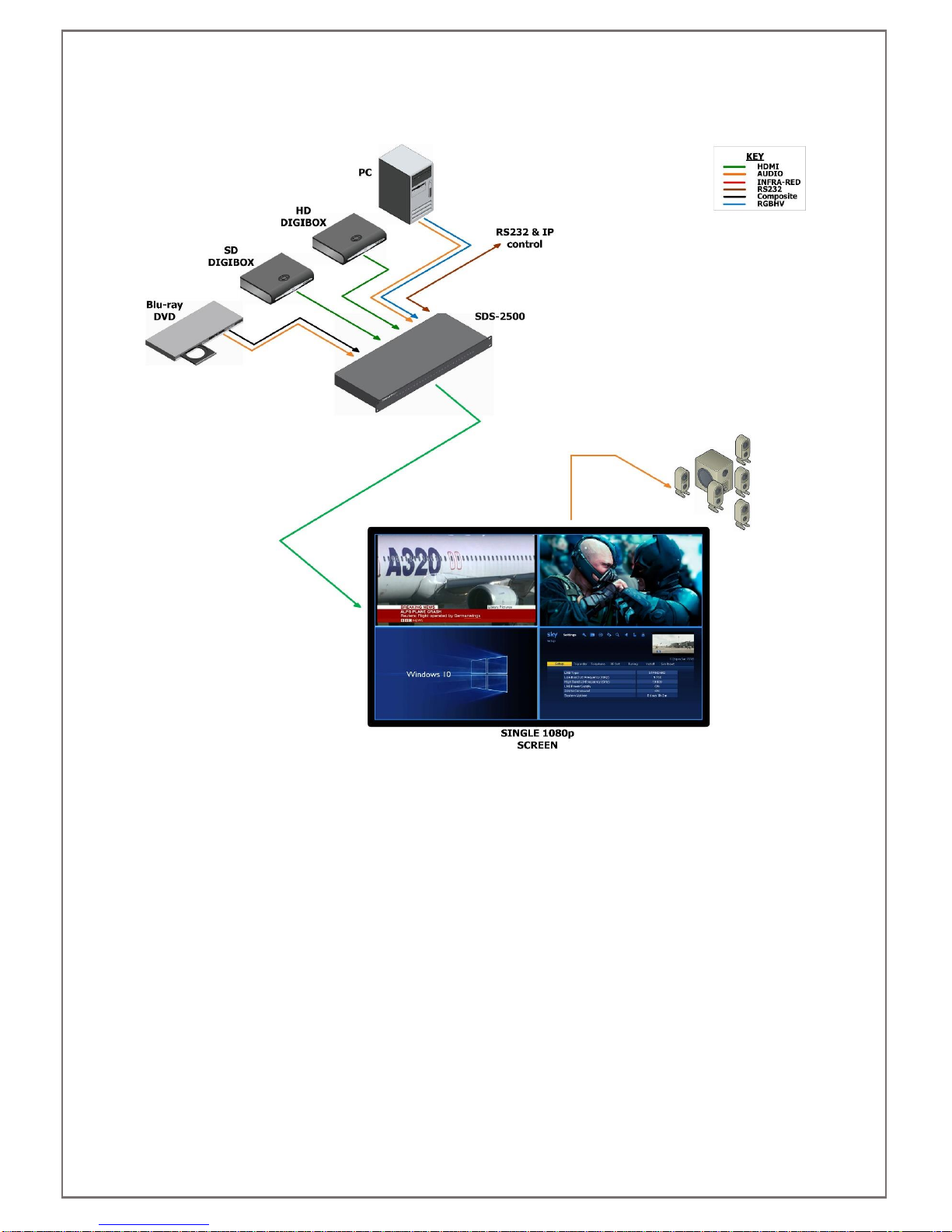
4.3 QUAD-SPLIT POP/PIP APPLICATION
Inhaltsverzeichnis


