Smith's Heating First Hydronic SS3 W Bedienungsanleitung

Space Saver
Discover the hidden benefits
Installation and User Guide
New
Space Saver

Installation Guide
2
Installation Guide
User Guide
Accessory
Hydronic 3
SS3 W
SS5 W
SS7 W
SS9 W
Hydronic Low Voltage 7
SS5 W/12V
Hydronic/Electric 11
SS5 W/Dual
Electric 16
SS2E W
Remote Room Thermostat 22
(Part No. RT002)
Hydronic &
Hydronic Low Voltage 18
SS3 W
SS5 W
SS7 W
SS9 W
SS5 W/12V
Hydronic/Electric 19
SS5 W/Dual
Electric 21
SS2E W
SS5 W/Dual
SS5 W/12V
SS9 W
Index

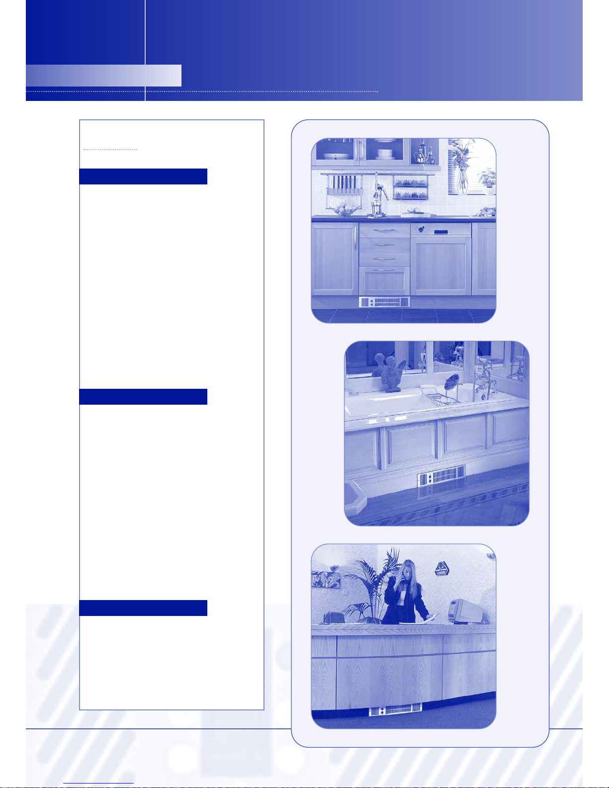
Space Saver is primarily intended for installation
in the space beneath kitchen cupboards behind
the plinth. However, it can also be installed in
similar applications such as stair risers and other
built-in furniture.
This Space Saver model must not be installed in a
bathroom or other high humidity areas. Please
contact us on 01245 324560 for details of products
suitable for these applications.
Space Saver is designed for use on standard two-
pipe pumped central heating systems. Pipes are
15mm and either may be used as flow or return.
This product is not suitable for one-pipe systems.
In line with best practice, isolating valves (not
supplied) must be fitted to the system flow and
return pipes. Failure to fit isolating valves may
mean that the product is not serviceable in the
event of failure.
Space Saver is classified as a fixed appliance and
electrical connection should be via a double pole
3A fused spur with a minimum contact gap of 3mm.
The fused spur must not be directly above the
heater but should be accessible after completion
of the installation. If the pre-wired mains cable is
damaged, it must be replaced by either the
manufacturer, its service agent or similarly
qualified persons. The appliance must be earthed.
To ensure adequate airflow, a minimum clearance
of 20mm between the top of the product and any
shelving is essential.
To avoid the possibility of vibration, this product
must be installed on a flat, even surface.
There must be no rear access to the product after
completion of the installation.
To conform with Building Regulations Part L (Part J
in Scotland), a remote room thermostat (Smith’s
Part No. RT002) can be used in conjunction with
this Space Saver fan convector.
Isolating valves (not supplied) should be fitted to
the flow and return pipes on the heater.
The flexible installation hoses supplied are suitable
for use with either 15mm diameter copper pipe or
15mm cross-linked polythene barrier pipe to
BS 7291. For all other types of pipes we
recommended the use of compression type fittings.
Please note the guarantee may be invalidated if
this product is not installed and used in
accordance with this guide.
SS3 W, SS5 W, SS7 W, SS9 W
The following items should be included in the carton:
v
vProduct complete with fixed white grille and pre-wired mains cable.
v
vFixing screws (2).
v
vOne pair flexible installation hoses (not included with SS3 models).
Overlay grilles which fit over the fixed white grille are available in different colours and finishes. Please
consult the price list for details. In the event of any items missing or visible damage, please contact us on
01245 324560.
We would be most grateful if you would leave this Installation & User Guide and the
Guarantee Registration Card with the owner of the property.
3

4
Installation Guide
1. We recommend the use of a kneepad when
installing this product. Cut the opening in
the plinth to the size shown in the table. Use
method A or B
4. Isolate electrical supply and connect the
heater electric cable to the fused spur
(3A). Ensure the fused spur is not directly
above the heater and is accessible after
installation is complete.
2. Fit isolating valves (not supplied) to the
system flow and return pipes. Failure to fit
isolating valves may mean that the product is
not serviceable in the event of failure.
Connect the flexible hoses between the
system pipework and heater. Open the
isolating valves and check for leaks.
Model Width A Height B*
SS3 W 475mm 96mm
SS5 W 475mm 96mm
SS7 W 475mm 96mm
SS9 W 570mm 96mm
* The overall height of the grille is 100mm. Use care
when cutting the opening
3. Vent air through the bleed screw.
A
B

5
1. Turn on the electrical supply at the fused spur.
2. Set the upper control switch on the fascia grille
to BLUE and lower switch to either I or II. The
fan will run.
3. Turn on the central heating system.
4. Set any room thermostat/s to maximum.
5. Set the lower heat output switch to I and the
Commissioning
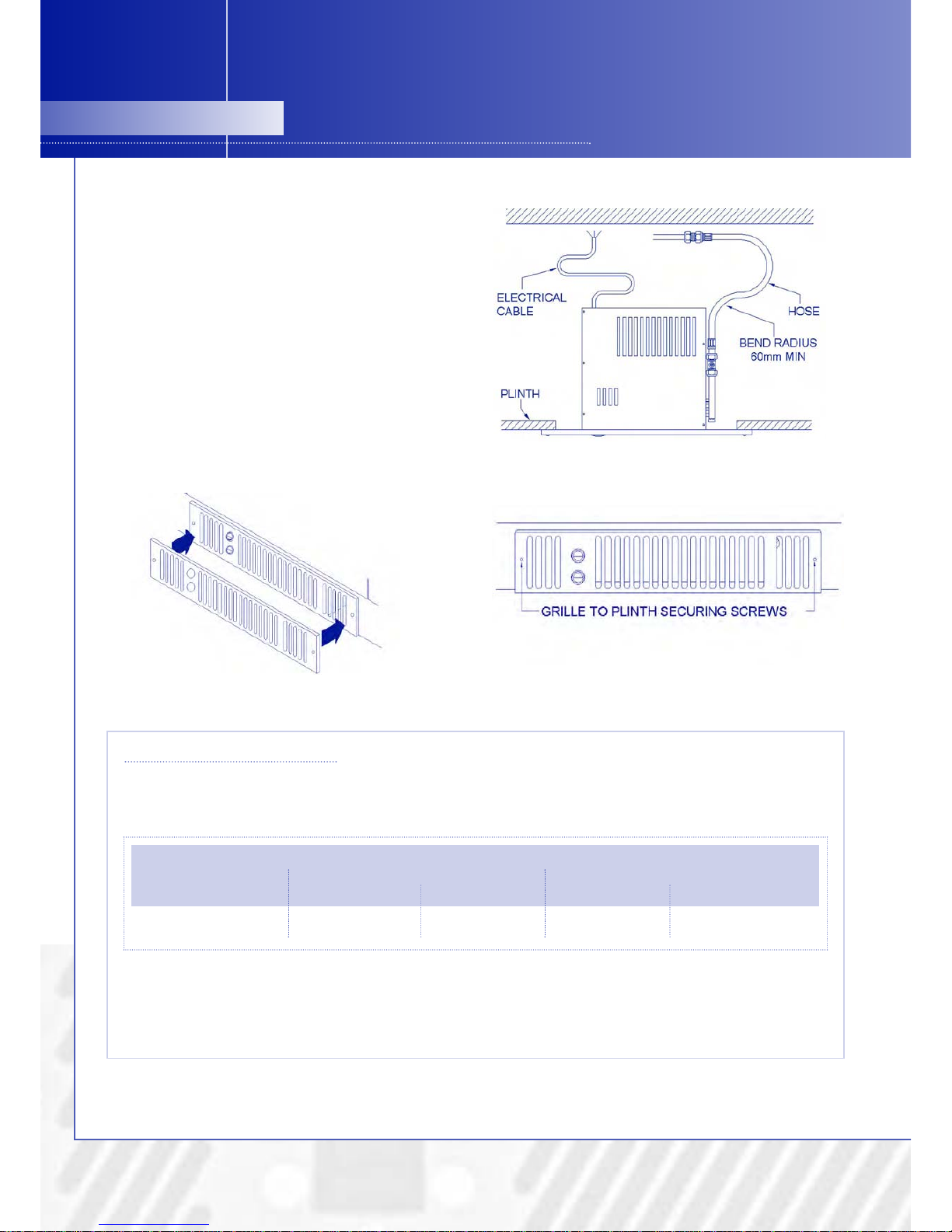
5. Position heater, making sure the flexible
hoses are not kinked and the electrical cable
is not snagged.
6a. Fit overlay grille (if supplied) over fixed grille 6b. Fix heater to plinth.
upper switch to RED — the fan should run and
heat will flow within a few minutes.
6. Balance the central heating system if Space
Saver is installed on the same circuit as panel
radiators.
7. When the installation is working correctly,
remember to reset any room thermostat/s to
its normal setting.

6
Installation Guide
Heat Output Performance
Fault Finding
In the event of any difficulty, please contact us on 01245 324560.
It will be more helpful if you do not remove the product from the central heating system.
It is recommended that the Space Saver model chosen is capable of maintaining the calculated heat loss
at normal heat output (I) enabling the boost setting (II) to be used for faster heat up.
Model Heat Output ∆
∆t 60ºC Heat Output ∆
∆t 50ºC
Normal Boost Normal Boost
(kW) (kW) (kW) (kW)
SS3 W 0.8 0.9 0.6 0.8
SS5 W 1.3 1.7 1.1 1.4
SS7 W 1.6 1.9 1.3 1.6
SS9 W 2.2 2.4 1.9 2.1
1. Fan does not run on any switch setting. a. Check the power supply is switched ON.
b. Check fuse in the fused spur.
c. Check the wiring connections at the fused spur.
2. No heat output on settings I and II. a. Check the power supply is switched ON.
b. If fitted, ensure any room thermostats are
calling for heat.
c. Balance the central heating system if installed
on the same circuit as panel radiators and
increase the circulating pump speed if required.
d. Increase the boiler water temperature.
Notes:
∆
∆
T 60ºC assumes a mean water temperature of 80ºC and room temperature of 20ºC.
∆
∆
T 50ºC assumes a mean water temperature of 70ºC and room temperature of 20ºC.

7
Space Saver 12-volt models are primarily intended
for installation in the space beneath bathroom
cabinets, bath panels and other high humidity
areas. 12-volt models are safe to operate with wet
hands.
Space Saver is designed for use on standard two-
pipe pumped central heating systems. Pipes are
15mm and either may be used a flow or return.
This product is not suitable for one-pipe systems.
The transformer must be located outside the
bathroom or high humidity area. The 450mm lead
attached to the transformer must be connected to
the fused spur (mains supply).
You will need to provide a cable (twin core 0.5mm2
for lengths up to 6 metres, 1.0mm2for longer
lengths) to connect the terminals on the product
to the transformer. The two single-pin male
connectors are provided to connect this cable to
the transformer terminals.
Space Saver is classified as a fixed appliance and
electrical connection should be via a double pole
3A fused spur with a minimum contact gap of 3mm.
The fused spur should be close to the transformer
and be accessible after completion of the
installation. This product must not be earthed.
To ensure adequate airflow, a minimum clearance
of 20mm between the top of the product and any
shelving is essential. To avoid the possibility of
vibration, this product must be installed on a flat
even surface. There must be no rear access to the
product after completion of the installation.
To conform with Building Regulations Part L (Part J
in Scotland), a remote room thermostat (Smith’s
Part No. RT002) can be used in conjunction with
this Space Saver fan convector.
The flexible installation hoses supplied are suitable
for use with either 15mm diameter copper pipe or
15mm cross-linked polythene barrier pipe to
BS 7291. For all other types of pipes we
recommended the use of compression type
fittings.
Please note the guarantee may be invalidated if
this product is not installed and used in
accordance with this guide.
The following items should be included in the carton:
v
vProduct with fixed white grille.
v
vTransformer with 450mm of pre-wired mains cable.
v
vTwo single-pin male connectors.
v
vFixing screws (2).
v
vOne pair flexible installation hoses.
Overlay grilles which fit over the fixed white grille are available in different colours and finishes. Please
consult the price list for details. In the event of items missing or visible damage, please contact us on
01245 324560.
We would be most grateful if you would leave this Installation & User Guide and the
Guarantee Registration Card with the owner of the property.
SS5 W/12V

8
Installation Guide
1. We recommend the use of a kneepad when
installing this product. Cut the opening in
the plinth to the size shown in the table.
Use method A or B.
Model Width A Height B*
SS5 W/12V 475mm 96mm
* The overall height of the grille is 100mm. Use care when
cutting the opening
2. Fit isolating valves (not supplied) to the
system flow and return pipes. Failure to fit
isolating valves may mean that the product is
not serviceable in the event of failure.
Connect the flexible hoses between the
system pipework and heater. Open the
isolating valves and check for leaks.
3. Vent air through the bleed screw.
A
B

9
4. Isolate electrical supply and connect the
transformer flying leads to the fused spur
(3A). The transformer must be located
outside the bathroom or high humidity
area. Connect the single-pin male
connectors to the twin core cable you have
supplied.
5. Push in the connectors to the transformer
terminals and connect the other end of the
cable to the terminals on the back of the
product.
1. Turn on the electrical supply at the fused spur.
2. Set the upper control switch on the fascia grille
to BLUE and lower switch to either I or II —the
fan will run.
3. Turn on the central heating system.
4. Set any room thermostat/s to maximum.
5. Set the lower heat output switch to I and the
Commissioning
upper switch to RED — the fan should run and
heat will flow within a few minutes.
6. Balance the central heating system if Space
Saver is installed on the same circuit as panel
radiators.
7. When the installation is working correctly,
remember to reset any room thermostat/s to
its normal setting.

10
Installation Guide
Heat Output Performance
7a. Fit overlay grille (if supplied) over fixed grille. 7b. Fix fascia grille to plinth.
It is recommended that the Space Saver model chosen is capable of maintaining the calculated heat loss
at normal heat output (I) enabling the boost setting (II) to be used for faster heat up.
6. Position heater, making sure the flexible
hoses are not kinked and the electrical cable
is not snagged.
Model Heat Output ∆
∆t 60ºC Heat Output ∆
∆t 50ºC
Normal Boost Normal Boost
(kW) (kW) (kW) (kW)
SS5 W/12V 1.3 1.7 1.1 1.4
Notes:
∆
∆
T 60ºC assumes a mean water temperature of 80ºC and room temperature of 20ºC.
∆
∆
T 50ºC assumes a mean water temperature of 70ºC an room temperature of 20ºC.
Dieses Handbuch passt für folgende Modelle
6
Inhaltsverzeichnis