SOLTEK SL-75MRN Series Bedienungsanleitung

4
Series SL-75MRN: 75MRN, 75MRN-R, 75MRN-L, 75MRN-RL
Contents
Chapter 1 Specification ............................................. 8
1-1. 75MRN / 75MRN-R / 75MRN-L / 75MRN-RL La out .....9
1-2. Mainboard Specifications ................................................... 10
1-2.1 CPU Socket ................................................................................... 10
1-2.2 S stem Chipsets ........................................................................... 10
1-2.3 Memor ......................................................................................... 10
1-2.4 BIOS............................................................................................... 10
1-2.5 Integrated AGP interface and additional AGP Slot .............. 11
1-2.6 Advanced S stem Power Management .................................... 11
1-2.7 Multi-I/O Functions .................................................................... 11
1-2.8 Expansion Slots ............................................................................ 12
1-2.9 AC’97 Audio Codec on board .................................................... 12
1-2.10 Hardware Monitor on board ................................................... 12
1-2.11 Serial ATA RAID Controller (75MRN-R / RL onl )............ 12
1-2.12 LAN on board (75MRN-L/ 75MRN-RL onl ) ...................... 12
1-2.13 Form Factor................................................................................ 12
1-3. Mainboard Specification Table .......................................... 13
1-4. Chipset S stem Block Diagram.......................................... 14
Chapter 2 Hardware Setup ..................................... 16
2-1 CPU Identification and Installation ................................... 17
2-1.1 CPU Identification Legends....................................................... 17
2-1.2 CPU Installation with Socket 462 ............................................. 18
2-2 Memor Installation ............................................................. 19
2-2.1 To Install DDR SDRAM Module .............................................. 19
2-2.2 Dual-channel DDR DIMM configuration................................ 20
2-2.3 To remove a DDR DIMM ........................................................... 20
2-3 VGA / AGP Slot Installation ................................................ 21

5
Contents
2-4 IDE Connector Installation ................................................. 22
2-5 Flopp Drive Connector Installation ................................. 23
2-6 Serial ATA Connectors (75MRN-R / 75MRN-RL Onl ) . 24
2-7 ATX Power Suppl Installation .......................................... 25
2-8 Jumper Settings ..................................................................... 26
2-8.1 How to tackle the Jumpers: ....................................................... 27
2-8.2 Jp2: CPU Clock Select ................................................................ 27
2-8.3 JBAT1: nVIDIA Clear CMOS ................................................... 28
2-8.4 Jp5: Anti-burn Shield (ABSII) .................................................. 29
2-8.5 Jp1&Jp7: PS/2 KB/Mouse Power On ...................................... 30
2-8.6 Jp4: SATA RAID Controller Select(75MRN2-R/RL Onl ) ..30
2-9 Other Connectors Configuration........................................ 31
2-9.1 Onboard FAN Connectors ......................................................... 31
2-9.2 USB Ports and USB Pin-headers .............................................. 32
2-9.3 Chassis Panel Connectors .......................................................... 33
2-9.4 PS/2 Mouse And PS/2 Ke board ............................................... 33
2-9.5 CD-ROM Audio Connectors ...................................................... 34
2-9.6 Thermal Resistors........................................................................ 34
2-9.7 Wake On LAN Connector: ......................................................... 35
2-9.8 COM 2 Header for one Serial Port........................................... 36
2-9.9 Complex Pin-header (Front Panel Connectors)..................... 37
2-9.10 6-channel Sound Output Connector (Optional)................... 39
2-9.11 LAN Connector (75MRN-L / 75MRN-RL Onl ) .................. 39
Chapter 3 Software Setup ....................................... 40
3-1 To Open up the Support CD ................................................ 41
3-2 To Install “nVIDIA nForce2 All in 1 Driver” ................... 42
3-3 To Install AC’97 Audio Driver ............................................ 44
3-4 To Verif 6-channel Audio.................................................... 45
3-5 DirectX Installation............................................................... 48
3-6 Graphics Driver Installation ............................................... 49

6
Series SL-75MRN: 75MRN, 75MRN-R, 75MRN-L, 75MRN-RL
3-7 To Install Hardware Monitor Utilit .................................. 50
3-7.1 Installation ................................................................................... 50
3-7.2 Verification .................................................................................. 51
3-8 To Install USB 2.0 Driver for Win2000 or WinXP........... 52
3-9 RAID Controller Drivers (75MRN-R / RL Onl ) ............ 53
Chapter 4 BIOS Setup............................................. 54
4-1 About BIOS Setup ................................................................. 55
4-2 To Run BIOS Setup ............................................................... 55
4-3 About CMOS .......................................................................... 55
4-4 The POST ( Power On Self Test ) ....................................... 55
4-5 To Upgrade BIOS .................................................................. 56
4-5.1 Before Upgrading BIOS ............................................................. 56
4-5.2 Upgrade Process........................................................................... 56
4-6 BIOS SETUP --- CMOS Setup Utilit ................................ 60
4-6.1 CMOS Setup Utilit .................................................................... 60
4-6.2 Standard CMOS Setup ............................................................... 61
4-6.3 Advanced BIOS Features ........................................................... 64
4-6.4 Advanced Chipset Features ....................................................... 68
4-6.5 Integrated Peripherals................................................................ 71
4-6.6 Power Management Setup ......................................................... 76
4-6.7 PnP / PCI Configuration ............................................................ 79
4-6.8 SmartDoc Anti-Burn Shield....................................................... 81
4-6.9 CPU Ratio/Voltage Control........................................................ 83
4-6.10 Load Optimized Defaults ........................................................ 85
4-6.11 SET SUPERVISOR / USER PASSWORD............................. 85
4-6.12 SAVE & EXIT SETUP .............................................................. 86
4-6.13 EXIT WITHOUT SAVING ...................................................... 86
Chapter 5 RAID Controller ................................... 87
5-0 Before Creating Disk Arra : ............................................... 88

7
Contents
5-1 Creating Your Disk Arra .................................................... 89
5-1.1 Creating An Arra For Performance/Securit ....................... 89
5-1.2 Creating Securit Arra With Existing Data Drive .............. 91
5-2 Installing Drivers................................................................... 93
5-2.1 For Windows 2000/XP ................................................................ 93
5-2.2 Windows 95/98 ............................................................................. 95
5-2.3 DOS/Windows 3.1x ...................................................................... 98
5-2.4 Windows NT4.0 ............................................................................ 99
APPENDICES........................................................ 101
Appendix-1 Identif BIOS Version & BIOS Part Number . 102
Appendix-2 Identif Mainboard Model Number ................. 103
Appendix-3 Technical Terms .................................................... 104
Item Checkup
• Mainboard
• User Manual (Mainboard)
• Multi-lingual Quick Installation Guide
• Support CD
• Bundled Bonus Pack CD
• Bundled Bonus Pack Manual
• Promise SATA RAID Driver Diskette (Optional)
• Cables :
ATA66/100/133 IDE Cable
FDD Cable
USB Cable (Optional)
2 x Serial ATA Cable (for 75MRN-R/75MRN-RL)
1x Serial ATA Power Cable (for 75MRN-R/75MRN-RL)
*****************************************************

16
Series SL-75MRN: 75MRN, 75MRN-R, 75MRN-L, 75MRN-RL
Chapter 2 Hardware Setup
1. We recommend to install your CPU before any other components.
For detailed installation instructions of processor, you can also refer
to the pamphlet enclosed in your CPU package.
2. Installing a cooling fan with a good heatsink is a must for proper heat
dissipation for your CPU. Get ready an appropriate fan with heatsink
for proper installation. Improper fan and installation will damage your
CPU.
3. In case CPU Vcore, CPU clock or Frequency Ratio is adjustable on
board, please follow the instructions described in the User Manual
for proper setup. Incorrect setting will cause damage to your CPU.
he following topics are included in this chapter:
o Get hings Ready for Hardware Setup !
2-1 CPU Identification and Installation
2-2 Memory Installation
2-3 AGP Slot Installation
2-4 IDE Connector Installation
2-5 Floppy Drive Connector ( FDC ) Installation
2-6 Serial A A Connector Installation (75MRN-R /
75MRN-RL only)
2-7 A X Power Supply Installation
2-8 Jumper Settings
2-9 Other Connectors Configuration
2-10 IRQ Description

17
Chapter 2 Hardware Setup
2-1 CPU Identification and Installation
2-1.1 CPU Identification Legends
AMD
XXXXXXXXXXX¤
XXXXXXXXXXXX¤
XXXXXXX¤
XXXXXXXXX¤
XXXXXXXXXXX¤
XXXX
0.18um CPU 0.13 um CPU
AMD
AMD AthlonTM
AXDA2400DKV3C RFBCY
A5280061
XXXXXXXXXXXXX XXXXXXXXXX
AMD Athlon(Duron)
AX 1900 D M 3 C
(1) (2) (3) (4) (5) (6) (7)
Family / Architecture:
A, AX, AXDA=AMD Athlon Processor
D, DHD, DHM, DHL=AMD Duron Processor
Speed: 1000=1000MHz, 1600=1400MHz, 1700=1467MHz,
1800=1533Mhz, 1900=1600MHz, 2000=1667MHz,
2100=1733MHz, 2200=1800MHz, 2400=2000MHz,
2600=2133MHz, 2700=2167MHz, 2500=1833MHz(Barton),
2800=2083MHz(Barton), 3000=2250MHz(Barton),
3200=2332MHz(Barton)
Package ype: A=CPGA, D=OPGA
Voltage: L=1.5V, U=1.6V, K=1.65V, P=1.7V, M=1.75V, N=1.8V
Maximum emperature: R=70˚C, Y=75˚C,V=85˚C
=90˚C, S=95˚C, Q=100˚C
Size of L2 Cache: 1=64Kb, 2=128Kb, 3=256Kb, 4=512Kb
Max FSB: A=B=200MHz, C=266MHz, D=333MHz, E=400MHz
Note: Get the Host CPU Clock by dividing FSB by 2.
(1)
(2)
(3)
(4)
(5)
(6)
(7)
18
Series SL-75MRN: 75MRN, 75MRN-R, 75MRN-L, 75MRN-RL
AMD
SOCKE 462
SOCKE 462
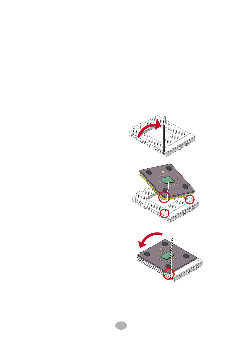
2-1.2 CPU Installation with Socket 462
This mainboard is built with CPU Socket 462 supporting the AMD CPUs
Athlon, Athlon XP and Duron:
• Follow the steps described in this section to install CPU into the on-
board Socket 462.
• After installation of CPU, you must also install a proper cooling fan
on top of the CPU and connect the Fan cable to the CPU fan
connector.
1. First pull sideways the lever of
Socket 462, and then turn it up
900 so as to raise the upper layer
of the socket from the lower
platform.
3. Make sure that all CPU pins have
completely entered the socket
and then lower down the lever
to lock up CPU to socket.
2. Configure Pin 1 of CPU to Pin 1
of the Socket, just as the way
shown in the diagram on the
right. Adjust the position of CPU
until you can feel all CPU pins
get into the pin holes of the
socket.
Pin 1
Pin 1
SOCKE 462
AMD

19
Chapter 2 Hardware Setup
184-Pin DIMM Notch Key Definitions
DRAM Key Position Voltage Key Position
2-2 Memory Installation
How to tackle the memory Modules:
• Make sure to unplug your power supply before adding or removing
memory module. Failure to do so may cause severe damage to both
your mainboard and the memory module.
• Pay attention to the orientation of the DIMM slots. Forcing a DIMM
into a slot improperly will damage the memory module and slot itself.
• Make sure you have the right type of memory module for your
mainboard.
• This series supports up to 3GB unbuffered DDR333/266 SDRAM,
with 3 DDR DIMM slots on board. Do not insert other type of mod-
ules into these slots.
• The nFORCE2 dual memory controller can double the DDR memory
bandwidth up to 6.4GB/s with DDR400, 5.4GB/s with DDR333 and
4.2GB/s with DDR266.
• To enable Dual-channel memory function, please see Dual-channel
Configuration” on next page.
• DDR DIMM slot has 184-pins and one notch. Insert a DDR SDRAM
vertically into the 184-pin slot with the notch-to-rib matching.
2-2.1 o Install DDR SDRAM Module
DDR Notch
Module Latch
DDR Rib

20
Series SL-75MRN: 75MRN, 75MRN-R, 75MRN-L, 75MRN-RL
nVIDIA
nFORCE2
DIM1
IDE2
IDE1
Li
Battery
nVIDIA
nFORCE2
AC'9 7
Codec
WOL1
1
PCI1
PCI5
PCI
PCI3
PCI2
Audio1
1
DIM2
PW1
SOCKET 62
RT2
DIM3
1
1
CDIN1
DDR 00/333/266MHz
RTL
ALC650
Fan2
1
Jp1
AGP1
BIOS
PW2
1
Jp2
RT1
JBAT1
1
1
Jp5
MCP
Fan1
¤
¤
LPC I/O
W83627HF
1 1
Master Dual Channel DIMM slot
¤
IGP
LPT1
COM1
PS/2
Mouse
(on top)
PS/2 Keyboard
(underside)
RJ45
(on top)
SB3
SB2
Line in
(on top)
Line Out
(middle)
Mic
(underside)
SB0
(on top)
SB1
VGA1
+12V Power
JA D1
1
(underside)
(middle)
ATX Main Power
SB0
(on top)
(underside)
1
10
COM2
Fan3
SPKRSTKeylock
HDD/LEDIRTX/IRRX PWRSMI
++
--
1
USB3
1
10
¤
PDC
20376
1
Jp
SATA1
SATA2
IDE3
1
FD1
1
Jp7
Master Dual-channel Slot
DIM3 (18 -pin)
2-2.2 Dual-channel DDR DIMM configuration
1. To enable Dual-channel function on this series of mainboard, a DDR
SDRAM module must be first inserted into DIM3, the Master Dual-
channel slot.
2. Next, either DIM1 or DIM2 or both should be inserted with DDR
SDRAM module(s) to activate the Dual-channel function. That is, DIM3
is the Master Dual-channel slot and at least one more slot is needed
to couple the Dual-channel function.
3. If Dual-channel configuration is set up, nFORCE2 dual memory con-
troller can double the DDR memory bandwidth up to 6.4GB/s with
DDR400, 5.4GB/s with DDR333 and 4.2GB/s with DDR266.
2-2.3 o remove a DDR DIMM
First power off the system and press down the holding latches on both
sides of DIMM slot to release the module..

21
Chapter 2 Hardware Setup
nVIDIA
nFORCE2
DIM1
IDE2
IDE1
Li
Battery
nVIDIA
nFORCE2
AC'9 7
Codec
WOL1
1
PCI1
PCI5
PCI
PCI3
PCI2
Audio1
1
DIM2
PW1
SOCKET 62
RT2
DIM3
1
1
CDIN1
DDR 00/333/266MHz
RTL
ALC650
Fan2
1
Jp1
AGP1
BIOS
PW2
1
Jp2
RT1
JBAT1
1
1
Jp5
MCP
Fan1
¤
¤
LPC I/O
W83627HF
1 1
Master Dual Channel DIMM slot
¤
IGP
LPT1
COM1
PS/2
Mouse
(on top)
PS/2 Keyboard
(underside)
RJ45
(on top)
SB3
SB2
Line in
(on top)
Line Out
(middle)
Mic
(underside)
SB0
(on top)
SB1
VGA1
+12V Power
JA D1
1
(underside)
(middle)
ATX Main Power
SB0
(on top)
(underside)
1
10
COM2
Fan3
SPKRSTKeylock
HDD/LEDIRTX/IRRX PWRSMI
++
--
1
USB3
1
10
¤
PDC
20376
1
Jp
SATA1
SATA2
IDE3
1
FD1
1
Jp7
2-3 VGA / AGP Slot Installation
The AGP slot on board supports 1.5V AGP 8X/4X card only. A Rib is
specifically added to the 8X/4X slot so as to match the AGP 8X/4X card.
To insert a 3.3V AGP 2X card into the AGP 4X slot will damage the
system chip and burn the 1.5V circuitry.
An AGP 8X card will support a data transfer rate up to 2GB/sec, while
an AGP 4X card will provide 1GB/sec transfer rate.
AGP Accelerator
notch
VGA
Connector
1.6V mode, up
to DDR 333
Analog
Monitor
2. To install additional AGP card into AGP 8X slot on board, users can
install either a 8X or 4X AGP card with its only card driver. AGP slot
on board is supported by 1.5V mode, with up to DDR 400 memory
module support.
1. To install on-board VGA, please connect your monitor directly to VGA
connector on board. VGA on board is supported by 1.6V mode, with
up to DDR 333 memory module support.
Dieses Handbuch passt für folgende Modelle
4
Inhaltsverzeichnis
Andere SOLTEK Computerhardware Handbücher


Beliebte Computerhardware Handbücher anderer Marken

EMC2
EMC2 VNX Series Betriebsanleitung

Panasonic
Panasonic DV0PM20105 Bedienungsanleitung

Mitsubishi Electric
Mitsubishi Electric Q81BD-J61BT11 Bedienungsanleitung

Gigabyte
Gigabyte B660M DS3H AX DDR4 Bedienungsanleitung

Raidon
Raidon iT2300 Bedienungsanleitung

National Instruments
National Instruments PXI-8186 Bedienungsanleitung


