sparkfun DEV-16885 Bedienungsanleitung

MicroMod All The Pins (ATP) Carrier Board
Introduction
Access All The Pins (i.e. ATP) of the MicroMod Processor Board with the MicroMod ATP Carrier Board!
Required Materials
To follow along with this tutorial, you will need the following materials. You may not need everything though
depending on what you have. Add it to your cart, read through the guide, and adjust the cart as necessary.
MicroMod Processor Board
You'll need a Processor Board to break out the pins.
SparkFun MicroMod ATP Carrier Board
DEV-16885

Accessories
At a minimum, you will need a USB C cable to power and program the boards. Depending on your application, you
may want to grab a Qwiic cable to connect a Qwiic-enabled device.
Tools
You will need a screw driver to tighten the screw between the processor board and carrier board.
SparkFun MicroMod Artemis Processor
DEV-16401
SparkFun MicroMod ESP32 Processor
WRL-16781
SparkFun MicroMod SAMD51 Processor
DEV-16791
SparkFun Qwiic Cable Kit
KIT-15081
USB 3.1 Cable A to C - 3 Foot
CAB-14743

Suggested Reading
If you aren't familiar with the MicroMod ecosystem, we recommend reading here for an overview. We recommend
reading here for an overview if you decide to take advantage of the Qwiic connector.
MicroMod Ecosystem Qwiic Connect System
If you aren’t familiar with the following concepts, we also recommend checking out these tutorials before
continuing.
Hardware Overview
MicroMod Processor Board
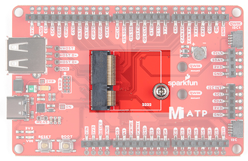
The MicroMod ATP Carrier Board includes a location for a MicroMod Processor Board. Here is where your chosen
Processor Board will reside.
SparkFun Mini Screwdriver
TOL-09146
Getting Started with MicroMod
Dive into the world of MicroMod - a compact interface
to connect a microcontroller to various peripherals via
the M.2 Connector!
New!

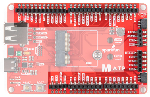
Power
There are a variety of power and power-related nets broken out to female header pins and their corresponding
through hole pads. The image below highlights those female headers and pads. The board can be powered from
the VIN pin with a recommended voltage between 3.3V to 6.0V. It can also be powered with 5V from the USB C
connector. The voltage is regulated down to 3.3V with the AP7361C voltage regulator to power your devices with
up to 1A of current. If your voltage is clean, and regulated, you can also connect it directly to the 3.3V line.
Backup Battery
The board has a built-in backup battery for Processor Boards with an RTC. Depending on the processor, it may
not be connected
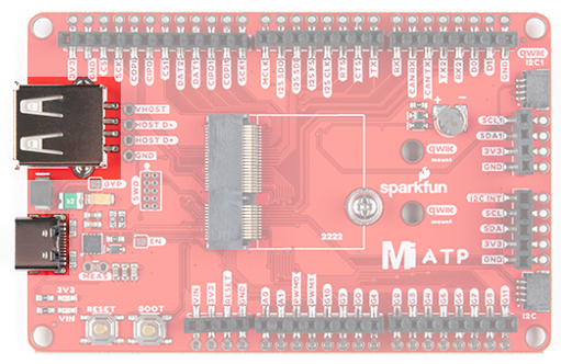
USB Ports
You have the option of connecting the board to a computer using the USB connectors. The USB Type C connector
is used to power, program the processor board, or pass serial data to a serial port. If your processor board has the
ability, there is also an option for USB host through the female USB Type A connector. There is a Schottky diode
on the USB host's 5V pin but we do not recommend connecting two both the Type C and Type A ports.

All the [GPIO] Pins
Remember our "All the Pins!" nickname? Well, we meant it. On the MicroMod ATP, not only have we broken out all
the major pins with female headers, we've added a secondary rail of plated through-holes alongside them to give
you the choice of either plug and play or soldering directly to the board. The general hardware pinout v1.0 is
broken out on the edge of the board. Your mileage may vary depending on the processor board that you are using.
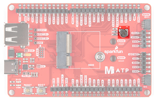
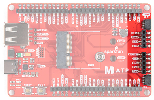
Qwiic and I C
There are two locations on the board for your favorite Qwiic-enabled device. IN addition to the Qwiic conenctors,
we also have pins that are broken out on the should you need to use jumeper wires or solder wire direction to both
boards. There are mounting holes for each standard 1.0"x1.0" Qwiic-enabled device.
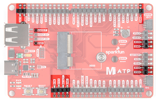
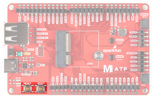
Reset and Boot Buttons
The reset button will reset the processor. The boot button will put the processor into a special boot mode.
Depending on the processor board, this boot pin may not be connected.
2

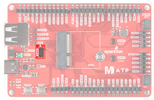
SWD Programming Pins
For advanced users, we broke out the SWD programming pins. Note that this is not populated so you will need a
compatible header and compatible JTAG programmer to connect.
Jumper Pads
There are a few jumpers populated on the board:
Bypass (BYP) - By default, the BYP is left open. Adding a solder jumper bypasses the 2A resettable fuse
on the back of the board should you decide to pull more than 2A from your USB source. Proceed with
caution should you decide to bypass the jumper.
Enable (EN) - By default, the EN pin is closed. This jumper is connected to a processor board's GPIO pin.
The processor board cna control the ATP's voltage regulator. Depending on the processor, this may not be
connected.
Current Measurement (MEAS) - By default, the MEAs is closed. Cutting the jumper and soldering to the
PTH pads will allow you to insert a current meter and precisely monitor the how much current your
application is consuming.
3V3 LED - By default, the 3V3 LED is closed. Cutting this jumper will disable the LED there is 3.3V.
VIN LED - By default, the VIN LED is closed. Cutting this jumper will disable the LED whenever there is an
input voltage.

General MicroMod Pinout
Wondering what the pins are that are broken out on the ATP MicroMod ATP Carrier Board? Check out the table
from the Getting Started with MicroMod for more information. Remember to check out the pins against your
Processor Board to determine what pins are available.
AUDIO UART GPIO/BUS I C SDIO SPI0 Dedicated
Name Bottom
Pin
Top
Pin
Name
(Not
Connected)
75 GND
3.3V 74 73 G5 / BUS5
RTC_3V_BATT 72 71 G6 / BUS6
SPI_CS1# SDIO_DATA3
(I/O)
70 69 G7 / BUS7
SDIO_DATA2
(I/O)
68 67 G8
SDIO_DATA1
(I/O)
66 65 G9 ADC_D- CAM_HSYNC
SPI_CIPO1 SDIO_DATA0
(I/O)
64 63 G10 ADC_D+ CAM_VSYNC
MICROMOD GENERAL PINOUT TABLE
MICROMOD GENERAL PIN DESCRIPTIONS
2

SPI COPI1 SDIO_CMD
(I/O)
62 61 SPI_CIPO
SPI SCK1 SDIO_SCK (O) 60 59 SPI_COPI (O) LED_DAT
AUD_MCLK
(O)
58 57 SPI_SCK (O) LED_CLK
PCM_OUT /
CAM_MCLK
I2S_OUT AUD_OUT 56 55 SPI_CS#
PCM_IN /
CAM_PCLK
I2S_IN AUD_IN 54 53 I2C_SCL1
(I/O)
PCM_SYNC
/
PDM_DATA
I2S_WS AUD_LRCLK 52 51 I2C_SDA1
(I/O)
PCM_CLK /
PDM_CLK
I2S_SCK AUD_BCLK 50 49 BATT_VIN / 3
(I - ADC) (0 /
3.3V)
G4 / BUS4 48 47 PWM1
G3 / BUS3 46 45 GND
G2 / BUS2 44 43 CAN_TX
G1 / BUS1 42 41 CAN_RX
G0 / BUS0 40 39 GND
A1 38 37 USBHOST_D-
GND 36 35 USBHOST_D+
A0 34 33 GND
PWM0 32 31 Module Key
Module Key 30 29 Module Key
Module Key 28 27 Module Key
Module Key 26 25 Module Key
Module Key 24 23 SWDIO
UART_TX2 (O) 22 21 SWDCK
UART_RX2 (I) 20 19 UART_RX1 (I)

Board Dimensions
The board is 3.30"x2.20". There are 4x mounting holes on each corner of the board.
Hardware Hookup
If you have not already, make sure to check out the Getting Started with MicroMod: Hardware Hookup for
information on inserting your Processor Board to your Carrier Board.
CAM_TRIG D1 18 17 UART_RX1 (0)
I2C_INT# 16 15 UART_CTS1
(I)
I2C_SCL (I/0)) 14 13 UART_RTS1
(O)
I2C_SDA (I/0) 12 11 BOOT (I -
Open Drain)
D0 10 9 USB_VIN
SWO G11 8 7 GND
RESET# (I -
Open Drain)
6 5 USB_D-
3.3V_EN 4 3 USB_D+
3.3V 2 1 GND
New!

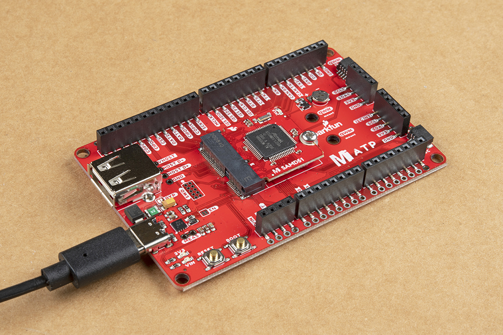
At a minimum, your setup should look like the image below. In this case, we had the MicroMod SAMD51
Processor Board secured in the M.2 connector. To program and power the microcontroller, we inserted the USB-C
cable.
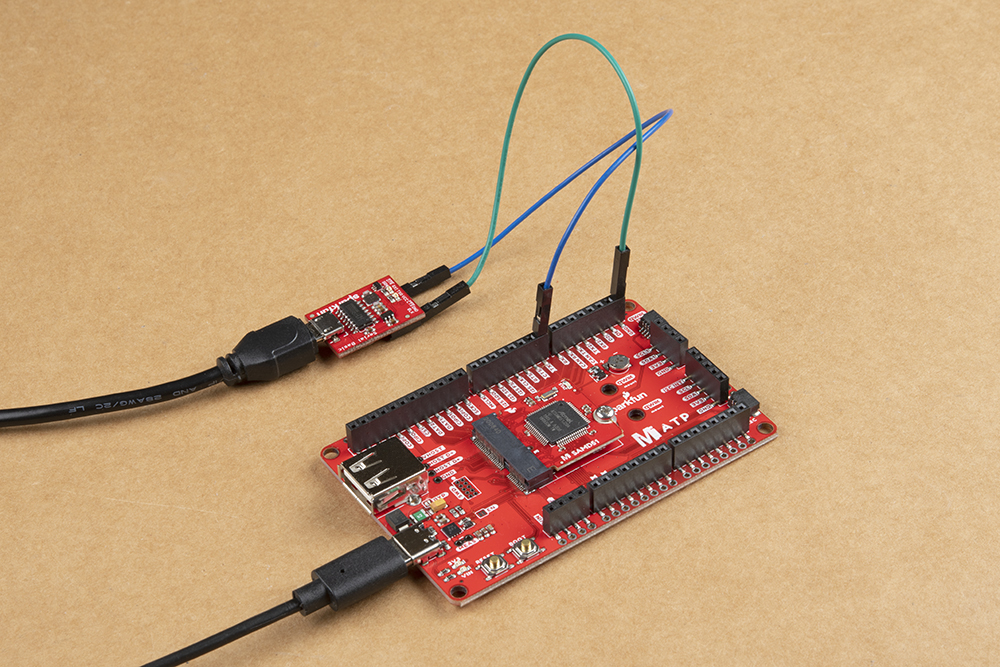
Depending on your setup you may need hardware (jumper wire, cables, header pins, breadboard, etc.) to connect
to the board. In this case, we used jumper wire to connect to another board.
To Qwiic-ly connect C devices, simply insert a Qwiic cable between the MicroMod ATP's Qwiic port and your
Qwiic device.
Getting Started with MicroMod
OCTOBER 21, 2020
Dive into the world of MicroMod - a compact interface to connect a
microcontroller to various peripherals via the M.2 Connector!
2
Inhaltsverzeichnis
Andere sparkfun Trägerplatine Handbücher


Beliebte Trägerplatine Handbücher anderer Marken

CTJ
CTJ TX2 Bedienungsanleitung

Amfeltec
Amfeltec AngelShark Series Bedienungsanleitung

Advantech
Advantech CPC-2420 Installations- und Betriebshandbuch

Bob's Space Racers
Bob's Space Racers BSR-3000 Bedienungsanleitung

RTimes
RTimes Z509 Bedienungsanleitung

mikroElektronika
mikroElektronika Clicker 2 Bedienungsanleitung


