L TN
Mountig:
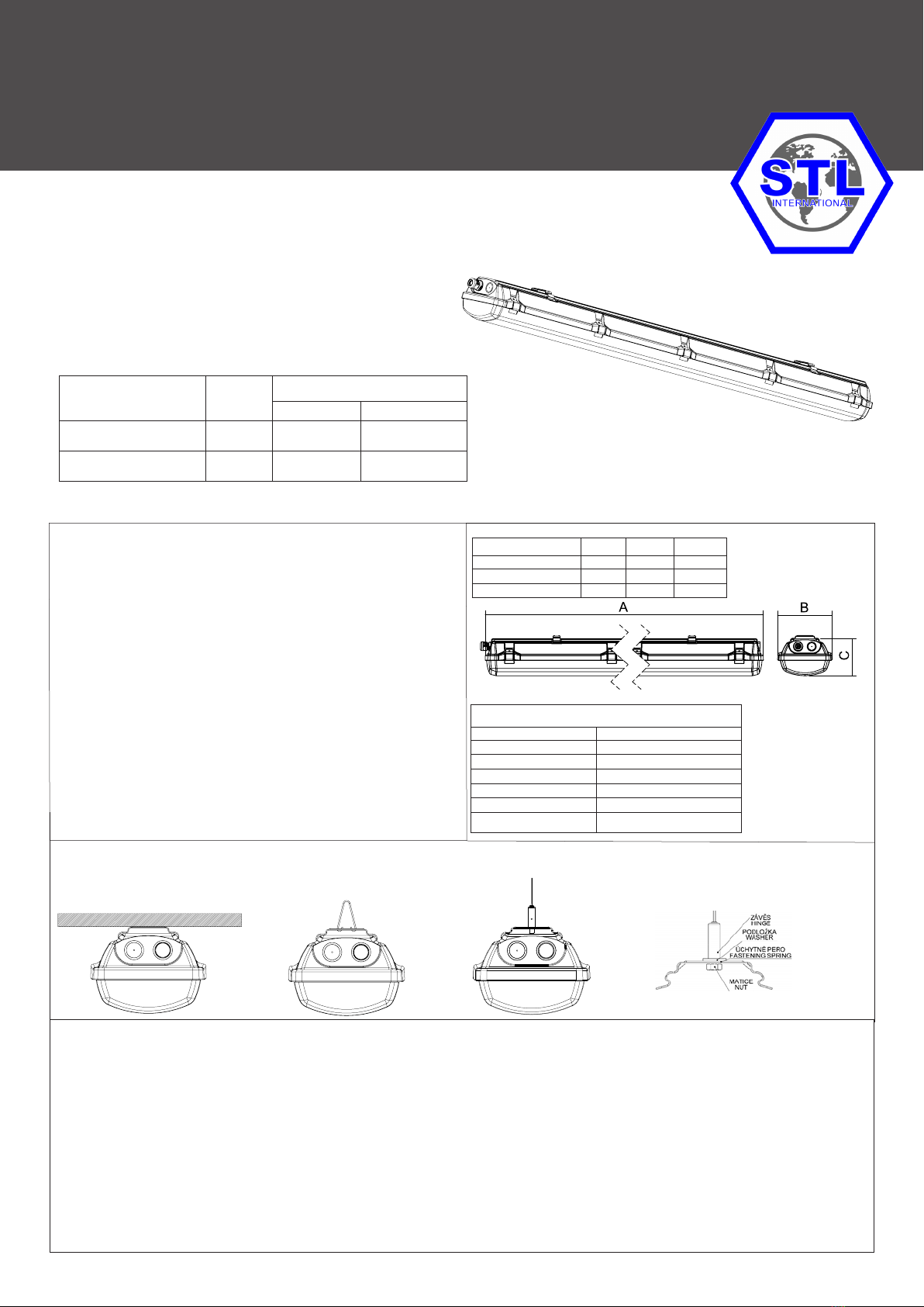
1. Remove reector from the luminaire.
2. Remove the bag with equipment.
3. The side opening in the body plant the cable gland (which is included in the luminaire equipment), and on the other side of her body screw the nut.Cable gland nut to the body, tighten torque 2,7Nm.
4. To the hinges on the body insert clips from equipment luminaire.
5. Fasten the lighting xture on the base: a) With fastening spring directly on the base pic. 1
b) With steel wire hanger (no included) pic. 2
c) With a cable suspension (no included) pic. 3.
Note: another method of fastening is not allowed!
6. Pull the power cable through the cable gland. Tighten bushings to a state of partial deformation of the rubber sealing washers, tightening torque 2,5Nm.Supply cable must have an outer diameter
in the range (see. Table sealing areas), which is a necessary condition for correct function of cable gland. Hole for power cable in the housing, which is not used cable gland (which is contained in the
equipment luminaires), seal blanking plug. In the luminaire is not allowed to use respiratory protective plugs and cable glands breathing
7.Connect the suppling cable to the free part of incoming terminal strip as follows:
EXTRA-N-LED EXTRA-N-LED-Em MULTIEXTRA-N-LED
Lphase
conductor
L1 cond. of charging
phase
L1 cond. of charging
phase
- - - - L2 cond. of switching
phase
Nneutral
conductor
Nneutral
conductor
Nneutral
conductor
Tprotective
conductor Tprotective
conductor Tprotective
conductor
* To each pole of terminal block can be connected two conductors in cut 0, 75 - 2, 5 mm2. In case of through-wiring connection it is necessary to use accessories for such connection!
In case that the label with the description of connection is glued on the reector of luminaire, you must do connection according this description.
8. Fasten reector back to plastic handles.
9. Insert the stainless clips (which are included in the equipment) into the prepared plugs on body.
10. Attach the glass cover on the xture:
- attach the optical cover that all round landed on a seal which is disposed in the xture
- Optical cover secure by the stainless steel clips, secure each clip with the screw included with the luminaire.
Table: List of cable glands:
Cable glands Diameter of the cable for cable glands
M25x1,5
OBO V-TEC Ex ∅ 7 mm - 12 mm
CEAG CHG 960 92.. P… ∅ 5,5 mm - 13 mm
WISKA ESKE/1 (S)(-L)(-*)(-RDE) ∅ 7 mm - 13 mm
ELFIT UNI ∅ 7 mm - 12 mm
BIMED LYRA (EURO-TOP) ∅ 7 mm - 12 mm
Page 2/3
Test of operation:
For correct operation it is necessary to observe enclosed instruction about testing of emergency xtures. Switch the luminaire o the mains voltage. The emergency LED module must light.
The green LED in the reector is o. Should the emergency lamp be extinguished within the test period though the battery is fully charged, the latter will have to be replaced by a new battery set.
Warning: The full battery capacity will be available after approximately three charging/discharging cycles.
Battery change:
"Replace the battery in a non-explosive environment"
Battery change is necessary when the xture doesn´t observe the conditions of rated operation period durability. In explosive area it is prohibited to disconnect battery for emergency unit. It is allowed to
disconnect the xture from supply voltage and take remove reector from the xture.
11. Disconnect the xture from supply voltage.
12. Remove reector from the housing.
13. Disconnect cable from terminal block.
14. Disconnect battery from emergency unit in non-explosive area as follows „-“black conductor and „+“red conductor.
15. Unbolt the nut of battery holder
16. Remove the old battery.
17. Screw the new battery (mark the date of operation start).
18. Connect conductors to battery as follows „+“red conductor and „-“black conductor.
19. Connect the xture to supply voltage.
20. Equip with reector and cover. Fix it with the clips.
WARNING: The battery in the xture can be changed for the same type or the same parameters only!!!