
Swann AMU-II ph/Redox Bedienungsanleitung

AMU-II pH/Redox
A-96.150.441 / 230523
AMU-II pH/Redox
Operator’s Manual

© 2023, Swan Analytische Instrumente AG, Switzerland, all rights reserved.
This manual applies to firmware V1.02 and higher.
The information contained in this document is subject to change without notice.
Customer Support
Swan and its representatives maintain a fully trained staff of technical specialists around
the world. For any technical question, contact your nearest Swan representative, or the
manufacturer:
Swan Analytische Instrumente AG
Studbachstrasse 13
8340 Hinwil
Switzerland
Internet: www.swan.ch
E-mail: [email protected]
Document Status
Title: AMU-II pH/Redox Operator’s Manual
ID: A-96.150.441
Revision Issue
00 May 2023 First edition

A-96.150.441 / 230523
AMU-II pH/Redox
1
Table of Contents
1. Safety Instructions . . . . . . . . . . . . . . . . . . . . . . . . . . . . . . . . . . . . . . . . . . . . . 3
1.1. Warning Notices . . . . . . . . . . . . . . . . . . . . . . . . . . . . . . . . . . . . . . . . . . . . . . . . 4
1.2. General Safety Regulations . . . . . . . . . . . . . . . . . . . . . . . . . . . . . . . . . . . . . . . 6
2. Product Description . . . . . . . . . . . . . . . . . . . . . . . . . . . . . . . . . . . . . . . . . . . . 7
2.1. Description of the System . . . . . . . . . . . . . . . . . . . . . . . . . . . . . . . . . . . . . . . . . 7
2.2. Single Components . . . . . . . . . . . . . . . . . . . . . . . . . . . . . . . . . . . . . . . . . . . . . . 10
2.2.1 AMU-II pH/Redox Transmitter . . . . . . . . . . . . . . . . . . . . . . . . . . . . . . . . . . . . 10
2.2.2 Flow Cell M-Flow 10-3PG . . . . . . . . . . . . . . . . . . . . . . . . . . . . . . . . . . . . . . . 11
2.2.3 Flow Cell QV-Flow SS316L pHRT . . . . . . . . . . . . . . . . . . . . . . . . . . . . . . . . . 12
2.2.4 Flow Cell B-Flow IS1000 . . . . . . . . . . . . . . . . . . . . . . . . . . . . . . . . . . . . . . . . 13
2.2.5 Swansensor pH and Redox Standard . . . . . . . . . . . . . . . . . . . . . . . . . . . . . . 14
2.2.6 Swansensor pH and Redox AY . . . . . . . . . . . . . . . . . . . . . . . . . . . . . . . . . . . 15
2.2.7 Swansensor pH and Redox SI. . . . . . . . . . . . . . . . . . . . . . . . . . . . . . . . . . . . 16
2.2.8 Swansensor pH and Redox FL . . . . . . . . . . . . . . . . . . . . . . . . . . . . . . . . . . . 17
2.2.9 Swansensor Reference FL . . . . . . . . . . . . . . . . . . . . . . . . . . . . . . . . . . . . . . 18
2.2.10 Spray Nozzle . . . . . . . . . . . . . . . . . . . . . . . . . . . . . . . . . . . . . . . . . . . . . . . . . 18
3. Installation . . . . . . . . . . . . . . . . . . . . . . . . . . . . . . . . . . . . . . . . . . . . . . . . . . . . 19
3.1. Mounting of the AMU-II Transmitter . . . . . . . . . . . . . . . . . . . . . . . . . . . . . . . . . 19
3.2. Electrical Connections. . . . . . . . . . . . . . . . . . . . . . . . . . . . . . . . . . . . . . . . . . . . 21
3.3. Power Supply . . . . . . . . . . . . . . . . . . . . . . . . . . . . . . . . . . . . . . . . . . . . . . . . . . 22
3.4. Sensor . . . . . . . . . . . . . . . . . . . . . . . . . . . . . . . . . . . . . . . . . . . . . . . . . . . . . . . . 22
3.5. Swan Flow Meter. . . . . . . . . . . . . . . . . . . . . . . . . . . . . . . . . . . . . . . . . . . . . . . . 22
3.6. Input . . . . . . . . . . . . . . . . . . . . . . . . . . . . . . . . . . . . . . . . . . . . . . . . . . . . . . . . . 23
3.7. Relay Contacts . . . . . . . . . . . . . . . . . . . . . . . . . . . . . . . . . . . . . . . . . . . . . . . . . 23
3.7.1 Alarm Relay . . . . . . . . . . . . . . . . . . . . . . . . . . . . . . . . . . . . . . . . . . . . . . . . . . 23
3.7.2 Relay 1 and 2. . . . . . . . . . . . . . . . . . . . . . . . . . . . . . . . . . . . . . . . . . . . . . . . . 23
3.8. Signal Output 1 and 2 (Current Outputs). . . . . . . . . . . . . . . . . . . . . . . . . . . . . . 24
3.9. Interface Options . . . . . . . . . . . . . . . . . . . . . . . . . . . . . . . . . . . . . . . . . . . . . . . . 25
3.9.1 Installation . . . . . . . . . . . . . . . . . . . . . . . . . . . . . . . . . . . . . . . . . . . . . . . . . . . 25
3.9.2 USB Option . . . . . . . . . . . . . . . . . . . . . . . . . . . . . . . . . . . . . . . . . . . . . . . . . . 27
3.9.3 RS485 Option . . . . . . . . . . . . . . . . . . . . . . . . . . . . . . . . . . . . . . . . . . . . . . . . 28
3.9.4 HART Option . . . . . . . . . . . . . . . . . . . . . . . . . . . . . . . . . . . . . . . . . . . . . . . . . 28
3.10. RS232 Interface . . . . . . . . . . . . . . . . . . . . . . . . . . . . . . . . . . . . . . . . . . . . . . . . 29
4. Instrument Setup. . . . . . . . . . . . . . . . . . . . . . . . . . . . . . . . . . . . . . . . . . . . . . . 30
4.1. Establish Sample Flow . . . . . . . . . . . . . . . . . . . . . . . . . . . . . . . . . . . . . . . . . . . 30
4.2. Programming. . . . . . . . . . . . . . . . . . . . . . . . . . . . . . . . . . . . . . . . . . . . . . . . . . . 30

A-96.150.441 / 230523
AMU-II pH/Redox
2
5. Operation . . . . . . . . . . . . . . . . . . . . . . . . . . . . . . . . . . . . . . . . . . . . . . . . . . . . . 32
5.1. Keys . . . . . . . . . . . . . . . . . . . . . . . . . . . . . . . . . . . . . . . . . . . . . . . . . . . . . . . . . . 32
5.2. Display . . . . . . . . . . . . . . . . . . . . . . . . . . . . . . . . . . . . . . . . . . . . . . . . . . . . . . . . 33
5.3. Software Structure . . . . . . . . . . . . . . . . . . . . . . . . . . . . . . . . . . . . . . . . . . . . . . . 34
5.4. Changing Parameters and values . . . . . . . . . . . . . . . . . . . . . . . . . . . . . . . . . . . 35
6. Maintenance . . . . . . . . . . . . . . . . . . . . . . . . . . . . . . . . . . . . . . . . . . . . . . . . . . . 36
6.1. Stop of Operation for Maintenance . . . . . . . . . . . . . . . . . . . . . . . . . . . . . . . . . . 36
6.2. Process Calibration . . . . . . . . . . . . . . . . . . . . . . . . . . . . . . . . . . . . . . . . . . . . . . 36
6.3. Standard Calibration . . . . . . . . . . . . . . . . . . . . . . . . . . . . . . . . . . . . . . . . . . . . . 38
6.4. Quality Assurance of the Instrument . . . . . . . . . . . . . . . . . . . . . . . . . . . . . . . . . 40
6.4.1 Activate SWAN Quality assurance procedure . . . . . . . . . . . . . . . . . . . . . . . . 41
6.4.2 Pre-test . . . . . . . . . . . . . . . . . . . . . . . . . . . . . . . . . . . . . . . . . . . . . . . . . . . . . . 42
6.4.3 Connect instruments. . . . . . . . . . . . . . . . . . . . . . . . . . . . . . . . . . . . . . . . . . . . 42
6.4.4 Carry out comparison measurement . . . . . . . . . . . . . . . . . . . . . . . . . . . . . . . 44
6.4.5 Completion of the measurement. . . . . . . . . . . . . . . . . . . . . . . . . . . . . . . . . . . 45
6.5. Longer Stop of Operation. . . . . . . . . . . . . . . . . . . . . . . . . . . . . . . . . . . . . . . . . . 46
7. Error List . . . . . . . . . . . . . . . . . . . . . . . . . . . . . . . . . . . . . . . . . . . . . . . . . . . . . . 47
8. Program Overview . . . . . . . . . . . . . . . . . . . . . . . . . . . . . . . . . . . . . . . . . . . . . . 50
8.1. Messages (Main Menu 1). . . . . . . . . . . . . . . . . . . . . . . . . . . . . . . . . . . . . . . . . . 50
8.2. Diagnostics (Main Menu 2) . . . . . . . . . . . . . . . . . . . . . . . . . . . . . . . . . . . . . . . . 51
8.3. Maintenance (Main Menu 3) . . . . . . . . . . . . . . . . . . . . . . . . . . . . . . . . . . . . . . . 52
8.4. Operation (Main Menu 4) . . . . . . . . . . . . . . . . . . . . . . . . . . . . . . . . . . . . . . . . . . 52
8.5. Installation (Main Menu 5) . . . . . . . . . . . . . . . . . . . . . . . . . . . . . . . . . . . . . . . . . 53
9. Program List and Explanations . . . . . . . . . . . . . . . . . . . . . . . . . . . . . . . . . . . 55
1 Messages . . . . . . . . . . . . . . . . . . . . . . . . . . . . . . . . . . . . . . . . . . . . . . . . . . . . 55
2 Diagnostics . . . . . . . . . . . . . . . . . . . . . . . . . . . . . . . . . . . . . . . . . . . . . . . . . . . 55
3 Maintenance . . . . . . . . . . . . . . . . . . . . . . . . . . . . . . . . . . . . . . . . . . . . . . . . . . 57
4 Operation . . . . . . . . . . . . . . . . . . . . . . . . . . . . . . . . . . . . . . . . . . . . . . . . . . . . 58
5 Installation . . . . . . . . . . . . . . . . . . . . . . . . . . . . . . . . . . . . . . . . . . . . . . . . . . . . 59
10. Default Values . . . . . . . . . . . . . . . . . . . . . . . . . . . . . . . . . . . . . . . . . . . . . . . . . 74
11. Notes . . . . . . . . . . . . . . . . . . . . . . . . . . . . . . . . . . . . . . . . . . . . . . . . . . . . . . . . . 77

A-96.150.441 / 230523
AMU-II pH/Redox
Safety Instructions
3
Operator’s Manual
This document describes the main steps for instrument setup,
operation and maintenance.
1. Safety Instructions
General The instructions included in this section explain the potential risks
associated with instrument operation and provide important safety
practices designed to minimize these risks.
If you carefully follow the information contained in this section, you
can protect yourself from hazards and create a safer work environ-
ment.
More safety instructions are given throughout this manual, at the
respective locations where observation is most important. Strictly
follow all safety instructions in this publication.
Target
audience
Operator: Qualified person who uses the equipment for its intended
purpose.
Instrument operation requires thorough knowledge of applications,
instrument functions and software program as well as all applicable
safety rules and regulations.
OM location Keep the Operator’s Manual in proximity of the instrument.
Qualification,
training
To be qualified for instrument installation and operation, you must:
read and understand the instructions in this manual as well as
the Material Safety Data Sheets.
know the relevant safety rules and regulations.
A-96.150.441 / 230523
AMU-II pH/Redox
Safety Instructions
4
1.1. Warning Notices
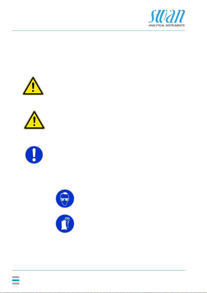
The symbols used for safety-related notices have the following
meaning:
DANGER
Your life or physical wellbeing are in serious danger if such warn-
ings are ignored.
Follow the prevention instructions carefully.
WARNING
Severe injuries or damage to the equipment can occur if such
warnings are ignored.
Follow the prevention instructions carefully.
CAUTION
Damage to the equipment, minor injury, malfunctions or incorrect
process values can be the consequence if such warnings are ig-
nored.
Follow the prevention instructions carefully.
Mandatory
signs
The mandatory signs in this manual have the following meaning:
Safety goggles
Safety gloves
A-96.150.441 / 230523
AMU-II pH/Redox
Safety Instructions
5
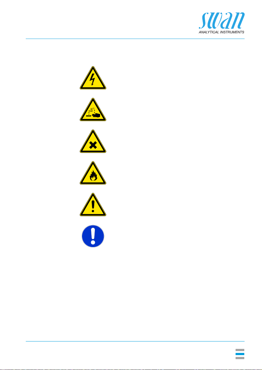
Warning signs The warning signs in this manual have the following meaning:
Electrical shock hazard
Corrosive
Harmful to health
Flammable
Warning general
Attention general

A-96.150.441 / 230523
AMU-II pH/Redox
Safety Instructions
6
1.2. General Safety Regulations
Legal
requirements
The user is responsible for proper system operation. All precautions
must be followed to ensure safe operation of the instrument.
Spare
parts and
disposables
Use only official Swan spare parts and disposables. If other parts are
used during the normal warranty period, the manufacturer’s
warranty is voided.
Modifications Modifications and instrument upgrades shall only be carried out by
an authorized service technician. Swan will not accept responsibility
for any claim resulting from unauthorized modification or alteration.
WARNING
Electrical Shock Hazard
If proper operation is no longer possible, the instrument must be
disconnected from all power lines, and measures must be taken
to prevent inadvertent operation.
To prevent from electrical shock, always make sure that the
ground wire is connected.
Service shall be performed by authorized personnel only.
Whenever electronic service is required, disconnect instrument
power and power of devices connected to.
– relay 1,
– relay 2,
– alarm relay
WARNING
For safe instrument installation and operation you must read and
understand the instructions in this manual.
WARNING
Only SWAN trained and authorized personnel shall perform the
tasks described in this document.

A-96.150.441 / 230523
AMU-II pH/Redox
Product Description
7
2. Product Description
2.1. Description of the System
Application pH and ORP are measured in many applications as for example
potable water, high purity water or waste water. Each application re-
quires different fittings, flow cells, and sensors.
pH measuring
principle
(simplified)
The pH measurement is based on a voltage measurement. A voltage
can only be measured between two different potentials, therefore,
the pH measuring chain contains a measuring electrode and a refer-
ence electrode. The reference electrode maintains a constant poten-
tial whereas the potential of the measuring electrode changes with
the pH value. The voltage which results from this potential difference
is measured and displayed on the transmitter as pH value. The mea-
suring chain is designed so that the voltage is zero at pH 7.
ORP measur-
ing principle
(simplified)
The ORP (redox) measurement is based on a voltage measurement.
A voltage can only be measured between two different potentials,
therefore, the ORP (redox) measuring chain contains a measuring
electrode and a reference electrode. The reference electrode main-
tains a constant potential whereas the potential of the measuring
electrode changes with the ORP value. The voltage which results
from this potential difference is measured and displayed on the
transmitter as ORP value in millivolt (mV).
Temperature
compensation
pH: The pH value depends on the sample temperature. To
compensate temperature fluctuations a temperature sensor is
installed in the flow cell.
ORP: Temperature compensation is not necessary.
Potable water, waste water: Compensation according to Nernst.
High purity water (power plant, semiconductor): Nernst or non-linear
solution temperature compensation, or linear compensation with co-
efficient.

A-96.150.441 / 230523
AMU-II pH/Redox
Product Description
8
Signal
outputs
Two signal outputs programmable for measured values (freely
scalable, linear, bilinear, log) or as continuous control output (control
parameters programmable).
Current loop: 0/4–20 mA
Maximal burden: 510 Ω
Relays Two potential-free contacts programmable as limit switches for
measured values, controllers or timer with automatic hold function.
Maximum load: 100 mA/50 V
Alarm relays Two potential-free contacts (one normally open and one normally
closed). Summary alarm indication for programmable alarm values
and instrument faults.
Normally open contact: closed during normal operation, open on
error and power loss.
Normally closed contact: open during normal operation, closed on
error and power loss
Maximum load: 100 mA / 50 V
Input One input for potential-free contact to freeze the measuring value or
to interrupt control in automated installations (hold function or remote
off).
Communica-
tion interface
RS232 interface for logger download with HyperTerminal
RS485 interface with fieldbus protocol Modbus or Profibus DP
(optional)
Safety
features
No data loss after power failure. All data is saved in non-volatile
memory. Overvoltage protection of inputs and outputs. Galvanic sep-
aration of measuring inputs from signal outputs.
pH electrode For the AMU-II pH/Redox four types of pH electrodes are available.
The Swansensor pH Standard is a combined gel electrode for
application in drinking water and swimming pools. Gel electrodes
can not be filled again and have a limited life time.
The Swansensor pH SI is a combined electrode with liquid
electrolyte (KCl) for the measurement of pH in power plants.
The Swansensor pH AY is a combined gel electrode for application
in waste water due to additional salt supplies
The Swansensor pH FL for the measurement of pH in high purity
water. This sensor can only be used in combination with
Swansensor Reference FL, A-87.860.100.
Inhaltsverzeichnis
Andere Swann Sender Handbücher


Beliebte Sender Handbücher anderer Marken


Dejero
Dejero EnGo 3x Bedienungsanleitung

Rosemount
Rosemount 4600 Bedienungsanleitung

Speaka Professional
Speaka Professional 2342740 Bedienungsanleitung

trubomat
trubomat GAB 1000 Bedienungsanleitung

Teledyne Analytical Instruments
Teledyne Analytical Instruments LXT-380 Bedienungsanleitung

Rondish
Rondish UT-11 Bedienungsanleitung


