Telecast Adder 161 Bedienungsanleitung

Telecast Fiber Systems, Inc.
102 Grove Street
Worcester, MA 01605
Tel: 508-754-4858
Fax: 508-752-1520
www.telecast-fiber.com
Adder™ 161
Audio Multiplexer
Instruction Manual

Adder™ 161
ii

Telecast Fiber Systems
Telecast Adder™ 161
Table of Contents
Introduction 1
Installation 1
Unpacking 1
Installation of Rack Mount Units 2
Line Power 2
Fiber and Coaxial Cable Runs 2
Transmitter Setup Procedure 3
Audio Signal Setup 3
Optimizing S/N Ratios 4
Receiver Setup Procedure 4
Optical Connections 6
Electrical Connections 7
Audio Connections 7
Digital Connections 8
48 VDC Phantom Power 9
Line Power Connection 9
Input Power Fuse 9
Battery Charging 10
Panel Indicators 10
Powering Up 11
Theory of Operation 11
Digital I/O Circuits, Data Connectors 1 and 2 12
Digital I/O Circuits, Data Connectors 3 and 4 12
Audio I/O Circuits, Audio Inputs 12
Audio I/O Circuits, Audio Outputs 15
Optical Outputs 15
Main Curcuits Explained 16
Accessory List 16
Troubleshooting 17
Specifications 18
Repair 19
Warranty 20
iii

Adder™161
iv
Figure 1. Installing the Rack Mount Adapters 2
Figure 2. TX Audio Setup Controls: Input Gain 4
Figure 3. RX Audio Setup Controls 4
Figure 4. Transmitter Main Circuit Board 5
Figure 5. Receiver Main Circuit Board 6
Figure 6. ST Optical Connectors, Rear Panel 7
Figure 7. XLR Connectors, Rear Panel 7
Figure 8. DB-9 Connectors, TX and RX, Rear Panel 8
Figure 9. Power Connector and Fuse Locations 9
Figure 10. TX and RX, Front Panel 10
Figure 11. Electronic Block Diagram 11
Figure 12. TX Digital Input Circuit (Connectors 1 & 2 only) 12
Figure 13. RX Digital Output Circuit (Connectors 1 & 2 only) 13
Figure 14. TX Audio Input Stage 14
Figure 15. Audio Output Circuit 15
Figure 16. Battery Charger Block Diagram 16
List of Figures
List of Tables
Table 1. Maximum Fiber Lengths 2
Table 2. Input Signal Levels 3
Table 3. XLR Audio I/O Cable Connections 7
Table 4. Digital Cable Connections 8
Table 5. Power Connections 9
Table 6. Output Signal Levels 15
Table 7. Adder 161 Main Circuits 16

Telecast Fiber Systems
Introduction
1
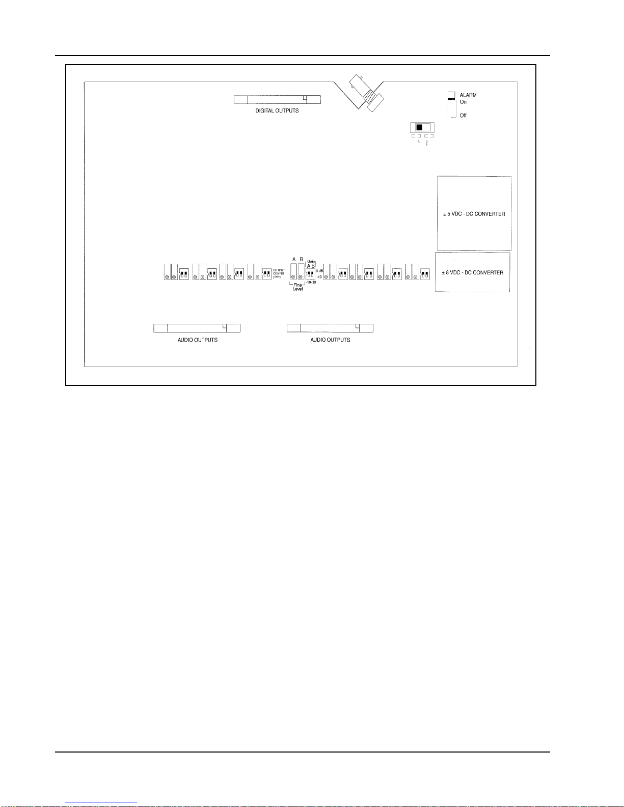
The Telecast Adder™161 System consists of an Adder 161 TX fiber optic transmitter/
multiplexer and an Adder 161 RX receiver/demultiplexer. The TX unit multiplexes and
sends up to 16 audio signals, two digital data signals, and four remote relay closures.
The RX unit receives the transmission and restores the analog signals. Audio inputs
are set up by internal DIP switches that set amplifier gain to accept either mic or line
level. Audio outputs are always at line level. Two of the four digital connectors provide
RS-422 and RS-232 compatible signals in one direction. The four digital connectors
also provide remote contact closures transmitted in one direction. An internal Ni-Cad
battery provides backup power in the event of line power loss.
The Adder 161 is available in a compact, lightweight 19 inch rack mount. The electrical
connections connections are discussed later in this manual.
Within an Adder 161 TX transmitter unit, the audio signals are first digitized and then
multiplexed with the digital control signals. The combined electrical signal is converted
to an optical signal and launched into the fiber optic cable. All signals are restored at
the receiver.
The Adder 161 TX has a port to allow clock synchronization with additional Telecast
products.
* TheAdder 161 also has a coaxial cable link that may be used as an alternate to the
fiber.
Installation
Unpacking
The Adder 161 System consists of:
•One Adder 161 TX Transmitter
•One Adder 161 RX Receiver
•Two external power supplies (AC/DC adapters)
•Plastic or metal covers for optical connectors
•Hardware kits for rack mount units
After unpacking, inspect the units for mechanical damage. Inspect all electrical
connectors for bent or damaged pins and latches. Report any damage to the carrier
and to Telecast Fiber Systems, Inc.
Leave the protective plastic caps on the optical connectors until it is time to attach the
fiber to the units. Store the caps for later use. Replace the caps on to the connectors
whenever the fiber is left disconnected.

Adder™161
Installation of Rack Mount Units
Units are shipped ready for bench use. All connections are made to the rear panel. To
mount a unit, rack ears must be attached. Each rack ear is held in place by two #10 flat
head screws (see Figure 1).
Figure 1: Installing the Rack Mount Adapters
Place each unit in its intended location before attaching any cables or wires. This will
prevent accidental damage to the cables or their connectors.
Line Power
The external power supplies require 120 VAC. Be sure that AC outlets are within reach
of their 6-foot power cords.
Fiber and Coaxial Cable Runs
The installer is responsible for providing the fiber optic cable runs, which are available
from Telecast Fiber Systems, Inc. The “Accessory List”, at the end of this manual,
contains part numbers for the cable and other items required for the system. Be sure
that the fiber core diameters are compatible with the intended installation distances as
shown in Table 1.
850 nm 1310/1550 nm
Table 1. Maximum Fiber Lengths
Fiber core diameter Maximum fiber length
50 microns 2 km 10 km
62.5 microns 3 km 8 km
8 microns (single mode) 20 km 20 km
2

Telecast Fiber Systems
The system units are factory configured for the fiber type to be used.
Inspect the fiber ends and clean them with clean, dry compressed air or with Kim-
Wipes that have been wet with isopropyl alcohol. Fingerprints or other dirt on the
optical connector end surfaces will reduce the received optical signal level.
If the system is to be used with a coaxial cable instead of an optical fiber, use Belden
type 8281, 75 coax, or equivalent. The maximum length for coax cable is 500 meters
(1640 feet).
600 balanced (low Zin) 10 K balanced (high Zin)
Unity +18 dBm peak Unity +16 dBV peak
+10 dB +8 dBm peak +10 dB +6 dBV peak
+20 dB -2 dBm peak +20 dB -4 dBV peak
+30 dB -12 dBm peak +30 dB -14 dBV peak
+40 dB -22 dBm peak +40 dB -24 dBV peak
+50 dB -32 dBm peak +50 dB -34 dBV peak
Audio Signal Setup
Note: Setting up the internal switches on the rack mount unit requires removal of its
top cover. The DIP switches should be set before installing the units in their racks.
The setup DIP switches for line or mic input levels are inside the Adder 161 TX on the
main circuit board. There are 16 switches, one for each channel.A representative DIP
switch is shown in Figure 2. Setup steps are not required if all inputs are at the factory
default of 600, 0 dB gain (line level). Setup steps are required if mic level inputs will
be used, if 10 K input impedance is required, or if an optional 10 dB boost is desired
at the TX.
The RX output default setting is 0 dB, unity gain. In the figures throughout this manual,
each switch is shown in its default position.
Table 2: Input Signal Levels
Transmitter Setup Procedure
3

Adder™161
1. Determine the appropriate TX input gain for each channel.
10 30 50
600
Ω20 40
Gain dB
Zin
Figure 2. TX Audio Setup Controls: Input Gain
2. With the power switch off, remove the top cover by removing the six #4 flat head
screws.
3. With the connector panel of the TX unit facing you, set the DIP switches as needed.
4. Replace the TX top cover and reinstall the screws.
Optimizing S/N Ratios
To obtain an improved noise floor in cases of low input signal levels (+ 8 dBm), the
input gain can be set to + 10 dB and the RX attenuation set to - 10 dB. Thus, the
signal levels remain at the same reference level throughout.
Receiver Setup Procedure
The setup switches for the output levels are inside the Adder 161 RX on the main
circuit board. The factory default is 0 dB.
1. With the power switch off, remove the top cover of the RX by removing the six #4 flat
head screws. In Figure 3, A refers to the odd numbered channel and B refers to the
even numbered channel of the audio pair.
2. Determine for which line outputs the 10 dB cut is to be used.
ƒ
Gain
−
10
−
10
ƒ
ABAB
Receiver
Output
Fine
Level
Figure 3. RX Audio Setup Controls: Trimpots and Gains
4

Telecast Fiber Systems
3. With the connector panel of the RX unit facing you, move the DIP switches as
needed.
4. Adjust the output signal levels to normalize the outputs using the Fine Level trim pot
in each output circuit of the Adder 161 RX. The range of adjustment is ± 2 dB.
5. If the system is to be used with coaxial cable rather than fiber, move the small switch
near the alarm switch on the PCB to the COAX position. See figure 5 for the exact
location.
6. Replace the RX top cover and reinstall the screws.
Figure 4. Transmitter Main Circuit Board
5

Adder™161
Refer to Figure 6 before beginning the optical connections. The fiber optic connections
to the TX and RX units are identical.
Figure 5. Receiver Main Circuit Board
Optical Connections
Connect the fiber to the Adder 161 at each end. If a coaxial cable is used instead of a
fiber, cap the optical connectors on the panels to protect them.
Assembled cables and connectors are available from Telecast Fiber Systems, Inc. For
custom cable fabrication, use type ST connectors such as Telecast part number
CONN-ST-QC. Always follow the connector manufacturer’s directions when fastening a
connector to the cable. A Quick-crimp kit, part number CKIT-ST-QC, is available from
Telecast.
The Adder 161 is compatible with industry standard ST type connectors. It may be
used with installed backbone cables or with dedicated cables.
WARNING! Never look directly into the end of the optical fiber while either end of the
system is operating. Eye damage is possible.
6
Inhaltsverzeichnis
Andere Telecast Multiplexer Handbücher
Beliebte Multiplexer Handbücher anderer Marken

ADTRAN
ADTRAN Frameport 768 Bedienungsanleitung

Elo TouchSystems
Elo TouchSystems E247 Bedienungsanleitung

Paradyne
Paradyne Hotwire 8786 Bedienungsanleitung

RFL Electronics
RFL Electronics 9508D UCC Bedienungsanleitung

Miranda
Miranda AMX-101i Bedienungsanleitung

ShipModul
ShipModul MiniPlex-AIX NMEA-0183 Bedienungsanleitung


