418 Users manual Release 1.03 – December 12, 2012
Part #74468
Printed in USA 5
1.4. Connection to Antenna &
Power Supply
The 418 is designed for use with any antenna
system providing 50 Ohm resistive
impedance at the desired operating frequency.
Every effort should be made to ensure the
impedance of the antenna system is as close
as possible to the specified 50-Ohm value.
Note: The “G5RV” type antenna and some
Windom’s do not provide 50-Ohm impedance
on all HF Amateur bands, and an external
wide-range antenna coupler may be needed
with this type antenna. Any antenna to be
used with the 418 must, ultimately, be fed
with 50 Ohm coaxial cable.
The 418 requires a source of well-filtered and
regulated DC voltage. The supply voltage on
the 418 is 13.8 Vdc nominal +/- 15% to allow
for mobile and battery operation. The
voltage source must be capable of supplying
23 amperes continuous duty. The model 940
or 941 TEN-TEC power supplies will meet or
exceed your voltage and current
requirements. We recommend using the
included DC power cable (P/N 46214). Use
of #12 stranded wire is recommended for
mobile and in home use to accommodate the
required current demand during transmit.
Note: Always enable the power source first
and then the amplifier. If a generator or
battery connected to a charger is used to
supply the DC source, always turn off the
amplifier before starting or shutting off the
DC source equipment. These recharging
devices often generate large voltage spikes
that can damage the amplifier.
1.5. A word about grounding
A good ground system is essential for
optimum operation of any HF transmitter.
The best solution is to connect all the station
equipment to a single ground connection.
Information on grounding can be found in the
ARRL Handbook. A good ground system can
contribute to the station efficiency in a
number of ways including minimizing the
possibility of electrical shock, and
minimizing RF currents flowing on the shield
of the coax cable causing interference to
electrical equipment and transceiver
accessories.
1.6. Philosophy of design
With the Model 418, Ten-Tec has created a
100 watt solid state silicon MOSFET
amplifier combining automatic or manual
control for ease of operation in the 160-
through 6-meter ham-band.
Refer to the Block Diagram in SECTION 7
for the following discussion. Receive signals
are routed through the antenna connectors
(Ant 1-2 or Ant 6) along to the antenna relays
then to the T/R relays. Signals then move on
to the lowpass filter board and finally the
Radio connector and transceiver.
Transmit signals are applied to the Radio
connector and routed to the T/R relays on the
lowpass filter board and then to the input
attenuator, input power bridge and frequency
counter. This transmitted signal is applied to
the 100 watt MOSFET amplifier and back to
the lowpass filter to be applied to the correct
filter and on to the antenna relays, finally
moving to the antenna connector Ant 1, 2, or
Ant 6.
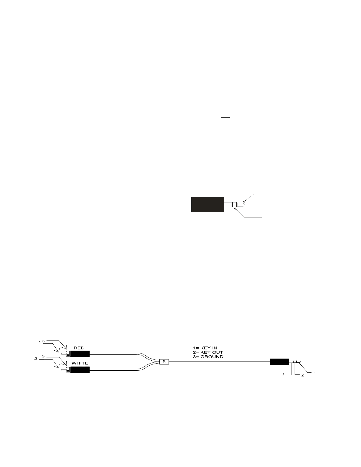
The PIC processor in the CPU module
executes firmware to perform functions such
as check input power and frequency, enable
bias to the MOSFET amplifier, checking
SWR, current, output power and temperature
based on the inputs from the front panel
buttons, key in jack or data from the ACC 1
connector. Cooling is achieved with the two
internal fans that are controlled by the CPU
that is monitoring the temperature of the
MOSFET heat sink.