THORLABS MLS203-1 Bedienungsanleitung

HA0264T
MLS203-1
Fast XY Scanning Stage
User Guide
Original Instructions

Page 0 22115-D02
MLS203 Series XY Scanning Stage
Contents
Chaper 1 Overview ..................................................................................................... 1
1.1 Introduction ........................................................................................ 1
Chaper 2 Safety .......................................................................................................... 3
2.1 Safety Information ............................................................................. 3
2.2 General Warnings .............................................................................. 3
Chaper 3 Installation .................................................................................................. 4
3.1 Unpacking ........................................................................................... 4
3.2 Mounting ............................................................................................. 4
3.2.1 General ................................................................................................... 4
3.2.2 Fitting the Finger Guards ........................................................................ 5
3.2.3 Mounting To Microscope ......................................................................... 5
3.3 Electrical Connections ...................................................................... 6
3.4 Dimensions ......................................................................................... 7
3.4.1 MLS203-1 Dimensions ............................................................................ 7
Chaper 4 Operation .................................................................................................... 8
4.1 General ............................................................................................... 8
4.2 Using the Kinesis software ............................................................... 9
4.3 Using the APT software ................................................................... 12
4.4 Position Error Messages. ................................................................ 14
4.5 Transportation .................................................................................. 15
4.6 Maintenance ..................................................................................... 15
4.7 Transportation .................................................................................. 15
Chaper 5 Specification ............................................................................................. 16
Chaper 6 Spares and Accessories .......................................................................... 17
6.1 Parts List ........................................................................................... 17
Chaper 7 Regulatory ................................................................................................ 18
7.1 Declarations Of Conformity ............................................................ 18
7.1.1 For Customers in Europe ...................................................................... 18
7.1.2 For Customers In The USA ................................................................... 18
7.2 CE Certificates ................................................................................. 19
Chaper 8 Thorlabs Worldwide Contacts ................................................................ 20

Rev F Apr 2019 Page 1
Chapter 1 Overview
Chapter 1 Overview
1.1 Introduction
The MLS203 uses internally integrated brushless DC servo motors with optical linear
encoders to provide an industry-leading, high-speed, compact scanning stage for
microscopy. This innovative design eliminates the external motor housings that create
mechanical clash points and impede access to the sample. It is ideal as a drop-in
upgrade replacement for the stage on Zeiss Axio Observer and Axiovert 40
microscopes.
The scanning stage can be positioned with a resolution of 0.1 µm and repeatability of
0.25 µm, at speeds up to 250 mm/s. The high-quality construction uses high-rigidity
precision linear bearings, commercial grade limit switches, and powerful brushless
linear DC servo motors. In addition, the number of moving parts has been minimized,
which optimizes the lifetime and reliability of the scanning stage.
Accessory plates are available for the stage to allow the positioning of standard
microscope slides and petri dishes, well plates and custom sample holders.
The MLS203 stages should be driven by the BBD series of brushless DC motor
controllers. These controllers include the Thorlabs apt software suite, which provides
an easy-to-use graphical interface for stand-alone operation as well as programming
support for integrated applications. The controller can also be used with most third
party software packages.
Fig. 1.1 MLS203 stage with MLS203P1 well plate adapter and 96 hole well plate
Page 2
MLS203 Series XY Scanning Stage
Chapter 2 Safety
2.1 Safety Information
For the continuing safety of the operators of this equipment, and the protection of the
equipment itself, the operator should take note of the Warnings, Cautions and Notes
throughout this handbook and, where visible, on the product itself.
The following safety symbols may be used throughout the handbook and on the
equipment itself.
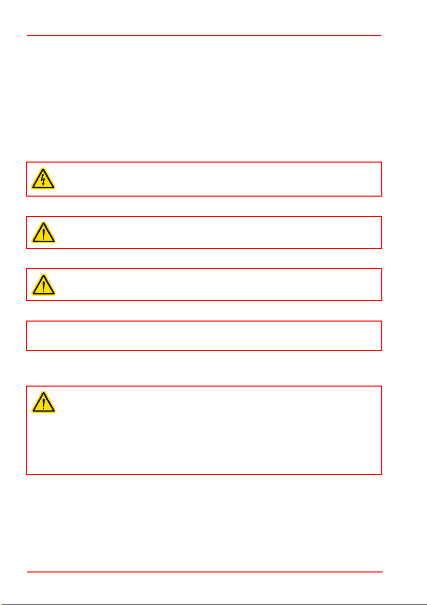
2.2 General Warnings
Warning: Risk of Electrical Shock
Given when there is a risk of injury from electrical shock.
Warning
Given when there is a risk of injury to users.
Caution
Given when there is a risk of damage to the product.
Note
Clarification of an instruction or additional information.
Warning
If this equipment is used in a manner not specified by the manufacturer, the
protection provided by the equipment may be impaired. In particular, excessive
moisture may impair operation.
Spillage of fluid, such as sample solutions, should be avoided. If spillage does
occur, clean up immediately using absorbant tissue. Do not allow spilled fluid to
enter the internal mechanism.

Rev F Apr 2019 Page 3
Chapter 3 Installation
Chapter 3 Installation
3.1 Unpacking
3.2 Mounting
3.2.1 General
Caution
Once removed from its packaging, the stage can be easily damaged by
mishandling. The unit should only be handled by its base, not by any
attachments to the moving platform.‘
Note
Retain the packing in which the unit was shipped, for use in future transportation.
Caution
The performance of the stage could be affected if the mounting surface is not
flat to within 200µm. Care should be taken when bolting the stage to the
microscope to ensure that the base plate does not warp, which could cause
stiffness to be experienced in the bearing rails. The attachment brackets for
mounting the stage to a particular microscope are supplied with shims, which
should be fitted as necessary - for more details see the instructions for fitting
the attachment brackets.
When mounting the stage close to other equipment, ensure that the travel of the
moving platform is not obstructed. If equipment mounted on the moving
platform is driven against a solid object, damage to the internal mechanism
could occur. The range of travel is as follows:
X-axis 110mm (4.3"), Y-axis 75mm (2.95”).
When considering the stage movement in the proximity of other objects or
equipment, ensure that movement of cables connected to the moving carriage
is not impeded.
When mounting equipment to the moving platform, always use the fixings
supplied with the equipment being fitted. If these are not available, do not use
fixings that protrude more than 2.5 mm below the bottom surface of the
equipment being mounted as this could damage the internal mechanism of the
stage.
Damaging the stage in this way could invalidate the warranty.

Page 4
MLS203 Series XY Scanning Stage
3.2.2 Fitting the Finger Guards
The stages are supplied with finger guards to avoid trapping of body parts or cables
in the mechanism. These should be fitted before the stage is mounted on the
microscope as follows:
1) Offer up the finger guards to the stage as shown below, and secure using the M3
x 16 bolts supplied.
Fig. 3.1 Fitting the finger guards
M3 x 16 screw (qty 6)

Rev F Apr 2019 Page 5
Chapter 3 Installation
3.2.3 Mounting To A Zeiss Axio Observer/ Axiovert 40 Series Microscope
The stages are mounted to the working surface by M4 screws through the base plate.
1) Remove the bolts securing the manual XY specimen stage, fitted as standard to
the microscope. Tilt back the lamp support unit as necessary.
2) Remove the manual XY specimen stage.
3) Place the stage onto the mounting platform and loosely fit the three M4 x 12 bolts
provided.
4) Check that the mounting surface is flat, and that the stage does not ‘rock’ when
opposing corners are pressed down.
5) If any rocking is present at item (4), fit shims supplied as necessary (see below)
until the mounting surface is level and no play is present.
6) Tighten the three M4 bolts to secure the MLS203 stage to the mounting platform
of the microscope.
Fig. 3.2 Zeiss Axio Observer/Axiovert 40 fitting
M4 x 12 bolt
(qty 3)

Page 6 22115-D02
MLS203 Series XY Scanning Stage
3.3 Electrical Connections
The stage must be driven by a Thorlabs BBD series controller. Connect the motor
leads to the MOTOR DRIVE connectors, and the encoder feedback leads to the
FEEDBACK connectors. Ensure that the motor drive and feedback leads for each
motor are connected to the correct channel.
Fig. 3.3 Electrical connections
Pin out information for the motor drive and encoder feedback connectors on the motor
flying leads is detailed below.
Fig. 3.4 Motor Drive and Feedback Flying Lead Pin Out Details
TRIG OUT
!
1 Motor Phase V
2 GND
3 Thermistor (not used)
4 Motor Phase U
5 Stage ID
6 GND
7 Motor Phase W
8 Enable
1
2 GND
3
4 Enc Index -
5 QB -
6 QA -
7 5 V
8 5 V
9 GND
10 Limit Switch +
11 Limit Switch -
12 Enc Index +
13 QB +
14 QA +
15 x
3
5
8
2
6
4
1
7
87654321
1514131211109
MOTOR DRIVE
ENCODER FEEDBACK

Rev F Apr 2019 Page 7
Chapter 3 Installation
3.4 Dimensions
3.4.1 MLS203-1 Dimensions
Fig. 3.5 MLS203-1 Dimensions
140.0mm
5.51in
115.0mm
4.53in
79.0mm
3.11in
54.0mm
2.13in
172.0mm
6.77in
72.0mm
2.83in
70.0mm
2.76in
112mm
4.4
APPROX
260.0mm
10.24in
120.0mm
4.72in
191.0mm
7.52in
170.5mm
6.71in
160.3mm
6.31in
214.0mm
8.43in
130.5mm
5.14in
125.0mm
4.92in
120.3mm
4.74in
58.5mm
2.30in
20.5mm
0.81in
M3X0.5 TAPPED HOLE
4 PLACES
M3X0.5 TAPPED HOLE FOR
MOUNTING MLS203P1-5
ACCESSORY PLATES 4 PLACES
OBJECTIVE CENTRE AND
CENTRE OF STAGE TRAVEL
MOUNTING HOLE FOR M5
CAP SCREW 4 PLACES
M3 x 0.5 TAPPED HOLE
6 PLACES
REMOVABLE GUARD
REMOVABLE GUARD
31.1mm
1.22in
10.0mm
0.39in
230.0mm
9.06in
X AXIS MOTOR AND
ENCODER CABLES
Y AXIS MOTOR AND
ENCODER CABLES
25.0mm
0.98in
ACCESSORY PLATE MOUNTING SURFACE
All dimensions in mm [in.]

Page 8
MLS203 Series XY Scanning Stage
Chapter 4 Operation
4.1 General
The stages are connected to the controller via 2 flying leads terminated in D-type
connectors (FEEDBACK) and 2 leads terminated in round 8-Pin DIN Connectors
(MOTOR DRIVE).
For a complete tutorial on using the stage, see the manual supplied with the controller.
Basic steps in controlling the stage are as follows:
1) Make electrical connections as detailed in Section 3.3.
2)
Move the moving platform a few times over its full range of travel to overcome any
storage resistance, then position the moving platform to be around its central p
osition.
3)
Power up the controller and wait for 10 secs until
the Channel Enable LEDs start
flashing.
4) If a joystick control is being used, press and hold the ‘High/Low’ button for 2
seconds, then release to home the stage. When homing is complete, the green
LED stops flashing.
5) If no joystick is being used, click the Home button on the GUI panel.
Caution
The MLS203 stages is designed to be driven by the Thorlabs BBD20x or
RBD201 Brushless DC Motor Controllers.
Warning
The motor controller must be switched OFF before the stages are plugged in or
unplugged. Failure to switch the controller off may result in damage to either the
controller, the stage, or both.
Warning
3-phase brushless DC motors are commutated electronically, i.e. the controller
drives the coils with a precisely controlled waveform, that depends on the
position of the rotor (or, with linear motors, the position of the coil housing). On
power up, the position of the coil housing is not known. The controller
establishes this by energising the coils and measuring the resulting movement.
This is why on power up, the stage (motor) may make a slight buzzing noise
and move about randomly for a few seconds. Phase initialization can only take
place if the motor can move unobstructed during this time. Before powering up
the BBD controller at item (2), ensure that the stage movement is unobstructed.
Inhaltsverzeichnis
Beliebte Scannerzubehör Handbücher anderer Marken

HP
HP Scanjet 5370C Series Bedienungsanleitung

imacon
imacon Flextight Damaged Original Kit Bedienungsanleitung

ARS-Imago
ARS-Imago POLAROID SCAN MASK Bedienungsanleitung

Epson
Epson B813112 Betriebsanleitung

Datalogic
Datalogic GFC-2 00 Series Bedienungsanleitung

Colortrac
Colortrac MK4 UNIVERSAL REPRO STAND Bedienungsanleitung


