
Trossen Robotics AG Series Anleitung zur Verwendung

Tel/Fax: 0755-82734836 www.dh-robotics.com
1
AG-95 Gripper
Short Manual (Modbus-RTU)
Content
Revisions...........................................................................................................................................2
1 Specifications.................................................................................................................................3
1.1 Performance Parameter .......................................................................................................4
1.2 Indicator ..............................................................................................................................5
1.3 Dimensions..........................................................................................................................5
1.4 Standard flange ...................................................................................................................6
1.5 Pinout Description...............................................................................................................6
2 Modbus-RTU Control ....................................................................................................................7
2.1 Wiring .................................................................................................................................7
2.2 Debugging software description .........................................................................................8
2.1.1 Installation and wiring of debugging software.........................................................8
2.1.2 Debugging software instructions..............................................................................9
2.3 Modbus-RTU Description.................................................................................................12
2.3.1 Default Communication Parameters ......................................................................12
2.3.2 RTU Framing .........................................................................................................13
2.3.3 Register Mapping...................................................................................................13
2.3.4 Register Description...............................................................................................15
2.3.4.1 Initialization ................................................................................................15
2.3.4.2 Force............................................................................................................15
2.3.4.3 Position........................................................................................................16
2.3.4.4 Initialization State .......................................................................................16
2.3.4.5 Gripper State ...............................................................................................17
2.3.4.6 Current Position ..........................................................................................17
2.3.4.7 Save Parameter............................................................................................18
2.3.4.8 Initialization Direction ................................................................................18
2.3.4.9 Slave Address..............................................................................................19
2.3.4.10 Baud Rate ..................................................................................................19
2.3.4.11 Stop Bits ....................................................................................................19
2.3.4.12 Parity .........................................................................................................20
2.3.4.13 Test I/O Parameters ...................................................................................20
2.3.4.14 I/O Mode Switch .......................................................................................21
2.3.4.15 I/O Parameter Configuration.....................................................................21
3 I/O Control...................................................................................................................................23

Tel/Fax: 0755-82734836 www.dh-robotics.com
2
Revisions
Date
Version
Revised content
20200426
V1.0
First edition, write wiring instructions and
command instructions
20200904
V2.0
Change some instructions , Update the description
of IO mode
20210401
V2.1
Normal update, Add debugging software
description
Tel/Fax: 0755-82734836 www.dh-robotics.com
3
1 Specifications
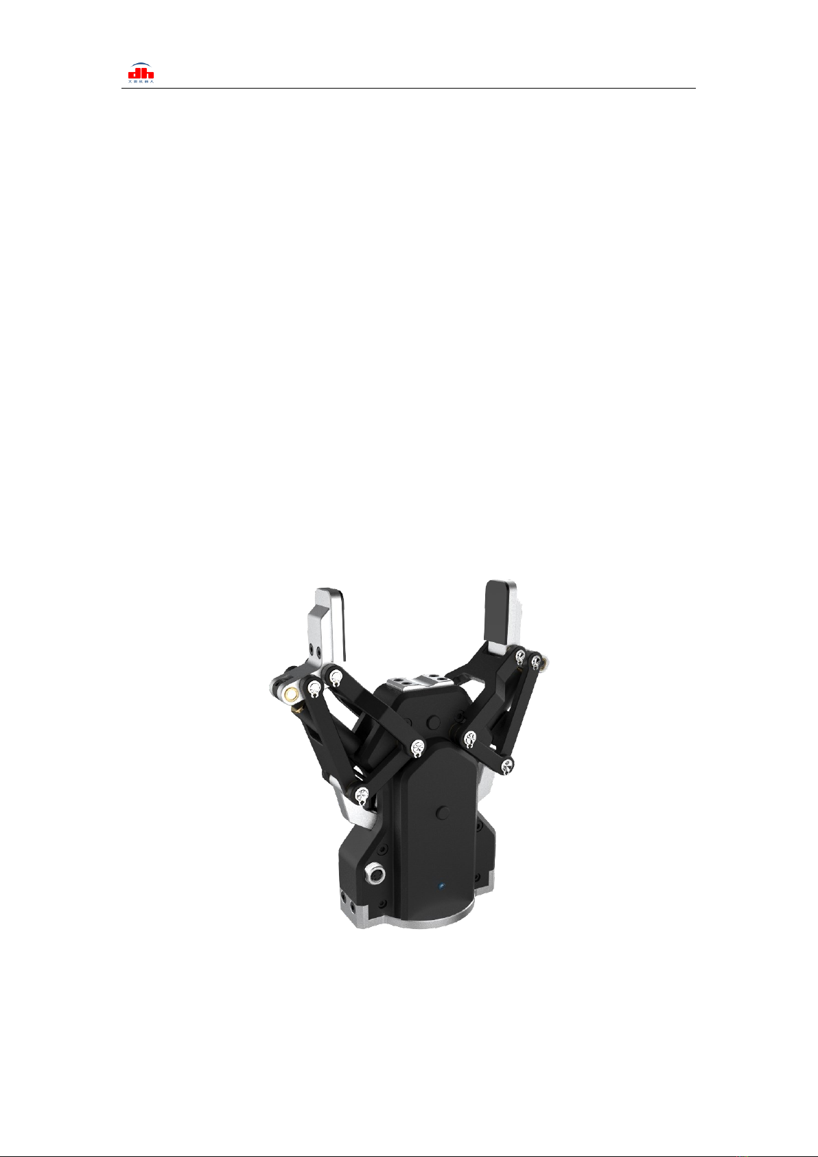
AG series are adaptive electric gripper, The number(AG-number) represents the maximum
gripping stroke of the gripper. The gripper is equipped with a pair of parallel fingertips, which runs
symmetrically during the movement. The main structure of the gripper is a smooth rectangular
structure. It is equipped with an 8-core communication interface, as shown in Figure 1.1. It has the
following characteristics:
Controllable force/position: The gripper can program and adjust the grip position and grip
force. In the process of gripper movement, the running speed is related to the clamping force. The
greater the clamping force is, the faster the running speed is.
Multiple communication modes: The gripper supports Modbus RTU protocol and IO mode
control. Other communication protocols such as USB and ETHERNET can be transferred through
protocol converter.
Gripping detection: The combination of force control and position control is adopted in the
gripping process.
Gripping feedback: The state of the gripper can be read by programming, and can also be
judged according to the indicator of the gripper.
Fingertips can be customized: Fingertips can be replaced according to situation, which is
suitable for precision machining, parts assembly, and other fields.
Figure 1.1 AG series gripper
Tel/Fax: 0755-82734836 www.dh-robotics.com
4
1.1 Performance Parameter
The specific parameters of AG-95 gripper are listed in Table 1.1.
Table 1.1 AG-95 specifications
AG-95 performance parameters.
Gripping force (per jaw)
45-160N
Opening/closing stroke (both sides)
0-98mm
Opening/Closing time
0.7s/0.7s
Weight
1kg
Position repeatability (both sides)
±0 .03mm
Noise emission
< 50 dB
Ingress protection rating
IP54
Communication protocols
Modbus RTU(RS485), I/O
Nominal voltage
24V DC±10%
Nominal current
0.8 A
Peak current
1.5 A
In the actual gripping, you should take the gripping angle and gripping position into account.
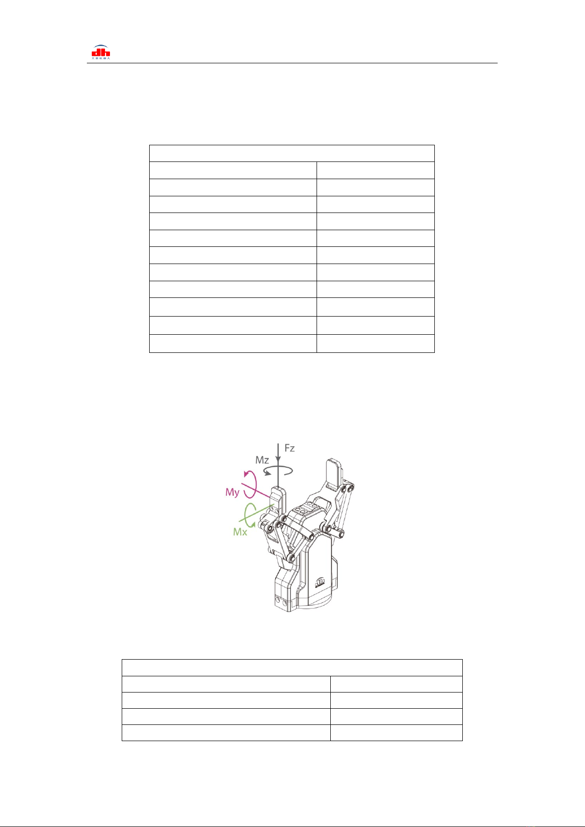
The following right-angle coordinate system is established, and the corresponding directions
of the X-axis, Y-axis, and Z-axis are shown in Figure 1.2 below. The force perpendicular to the
gripped flat surface is used as Fz, the x-axis direction torque is Mx, the y-axis direction torque is
My, and the z-axis direction torque is Mz. The AG-95 finger load table is shown in Table 1.2:
Figure 1.2 Finger load diagram
Table 1.2 AG-95 Finger load.
AG-95
Max allowable vertical load (static)
300N
Max allowable moment Mx (static)
4.75 N·m
Max allowable moment My (static)
4.75 N·m
Max allowable moment Mz (static)
4.75·N·m
Tel/Fax: 0755-82734836 www.dh-robotics.com
5
1.2 Indicator
The gripper can feed back the state of the gripper in real time. In addition to the command
reading, it can also be judged on the color of the indicator:
1.3 Dimensions
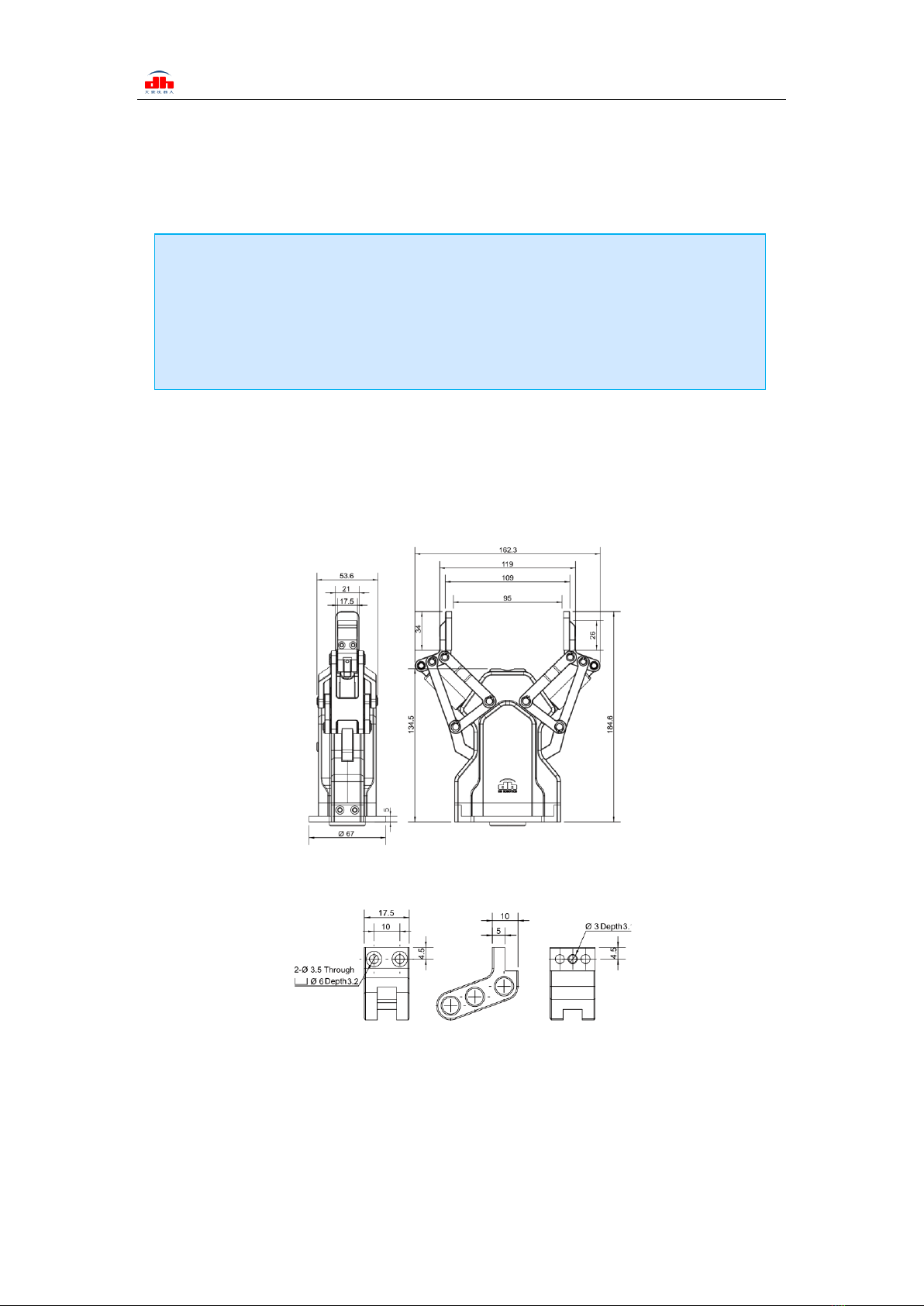
The gripper hardware parameters contain the specific size of the gripper, the mounting hole, as
shown in Figure 1.3(a), Figure 1.3(b).
Figure 1.3 (a) Dimension drawing of AG-95
Figure 1.3 (b) Finger-tip installation dimension drawing
Color description of indicator
·Uninitialized state: Red light blinks, other lights are off.
·Initialized State: the blue light is always on, indicating that it is in the operable state.
·Received command state: the red light blink once quickly (because the blue light is
always on at this time, the gripper indicator light will looks like a purple light).
·Object caught state: green light is always on, other lights are off.
·Object dropped state: green light blinking.

Tel/Fax: 0755-82734836 www.dh-robotics.com
6
1.4 Standard flange
The flange is used for the connection between AG-95 electric gripper and robot. The company
provides standard flange, as shown in Figure 1.4. The gripper also supports custom flanges.
Figure 1.4 Standard flange according to ISO 9409-1-50-4-M6
1.5 Pinout Description
The pinout of the gripper is shown in Figure 1.5, and the pin description is shown in
Table 1.3.
Figure1.5 Pinout assignment
Table 1.3 Pinout assignment
Wire number
Wire color
Description
1
White
485_A
2
Brown
485_B
3
Green
OUTPUT 1
4
Yellow
OUTPUT 2
5
Grey
24 V
6
Pink
INPUT 2
7
Blue
INPUT 1
8
Red
GND
Tel/Fax: 0755-82734836 www.dh-robotics.com
7
2 Modbus-RTU Control
2.1 Wiring
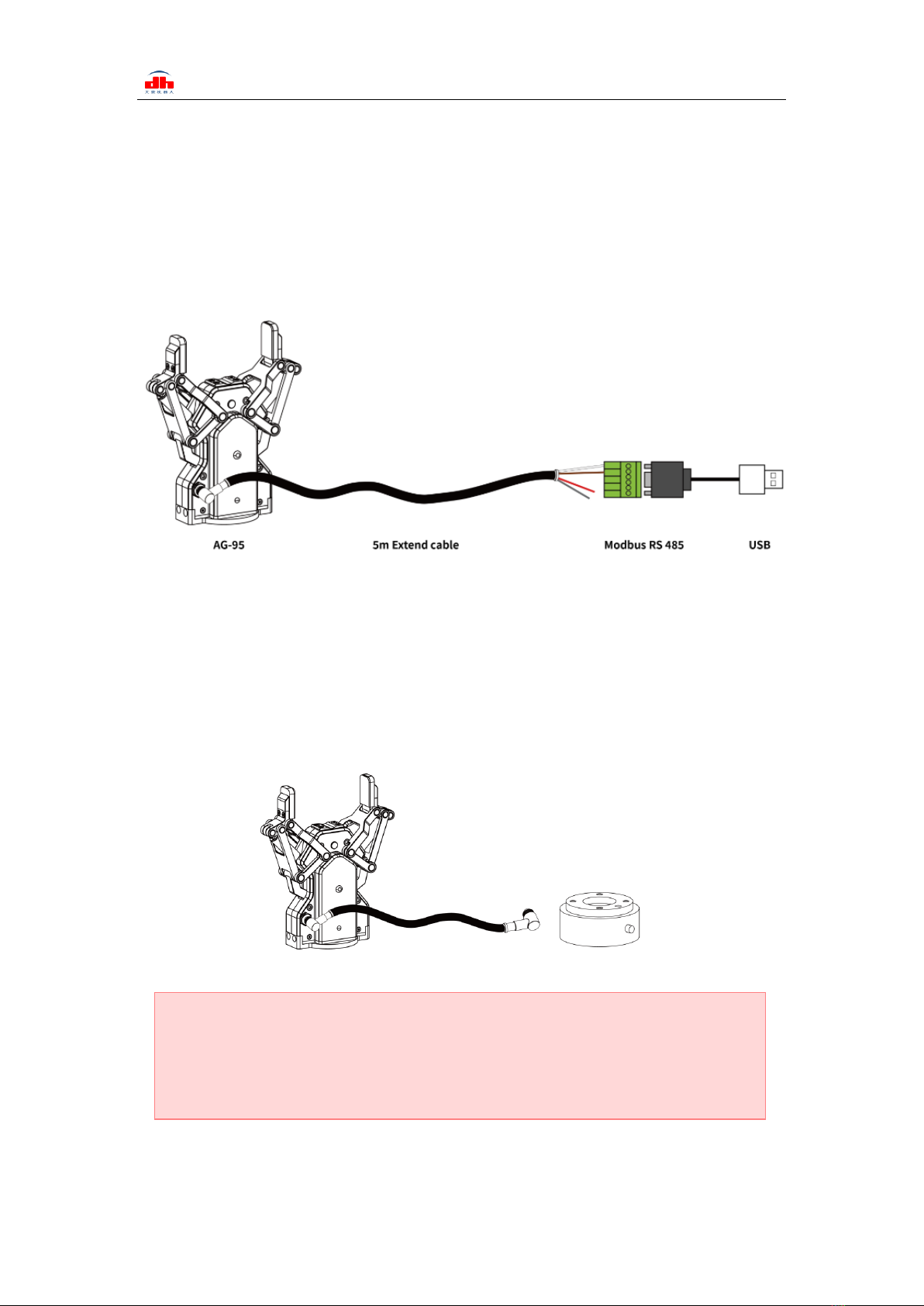
Use the provided RS-485 to USB converter (see the schematic in Figure 1.1 below) to plug
into a PC or other Controllers.
Figure 2.1 RS485 Connection
The outgoing line of clamping claw body can be changed according to the needs of
customers. For the cooperative robot with RS485 or IO interface at the end of the cooperative
robot, and using the front-end interface robot of M8, the aviation plug of M8 can be customized
for connection. When it needs to be extended, the aviation plug of M8 can be used for extension.
This plan needs to be confirmed with our company, as shown in the figure below:
Figure 2.2 Connecting the end of the robot
Warning
·Please check the connector before inserting, and do not forcibly insert the plug. Even if
the cable connector has a fool-proofing design, but you can still forcibly insert it, then the
gripper would be damaged.

Tel/Fax: 0755-82734836 www.dh-robotics.com
8
2.2 Debugging software description
The debugging software is specially used to control the gripper and set debugging parameters
on the computer. Because there is no RS485 interface in the computer, the USB to 485 module is
needed to convert the interface to USB interface, which is convenient for the debugging and
control of the gripper in the computer.
2.1.1 Installation and wiring of debugging software
Connecting by debugging software is essentially controlled by RS485 interface. The specific
connection needs to be connected to the 24 V, GND, 485_ A(T/R+,485+) , 485_ B (T / R -, 485 -) 4
wires in total. The power supply is a 24 V DC regulated power supply. Plug the USB port of the
module into the USB port of the computer. The wiring definitions of different series are different.
Please connect according to the instruction of specific clamping claw, as shown below:
Figure 2.3 RS485 Connection
Software can be downloaded on the official website. Software and driver are integrated in the
process of software installation, and both are installed together. It is recommended to check the
create shortcut during installation.
Wiring instructions
·① : when the device (computer) has RS485 interface, the communication can be directly
connected to RS485_A and RS485_B communication lines without transferring to 485
module through USB
·② : in this way, other serial port debugging software (such as MODBUS poll) can be
used for debugging

Tel/Fax: 0755-82734836 www.dh-robotics.com
9
Figure 2.4 (a) installation interface 1
Figure 2.4 (b) driver installation interface
2.1.2 Debugging software instructions
‘Before use, it is necessary to connect the corresponding wiring according to the instructions
(see 2.1.1 Installation and wiring of debugging software).
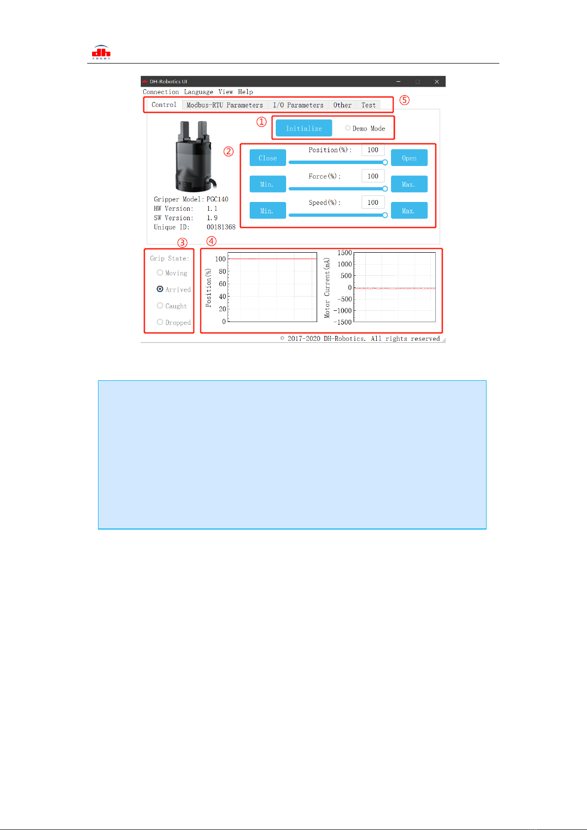
Open the software, the software will automatically identify the serial port, baud rate, ID number
and other information of the gripper for automatic connection. As shown in the figure below:
Tel/Fax: 0755-82734836 www.dh-robotics.com
10
Figure 2.5 main control interface
The specific interface description is as follows:
The gripper body uses Modbus RTU for communication, and can read and write data into the
register. The data can be read and written at the view register. The data includes control, feedback,
user parameters and I/O parameters as shown in the following figure:
Interface description
·① Initialization and demonstration mode: the gripper needs to be initialized before
operation to calibrate the zero point. The demonstration mode is a cyclic program.
·② Control interface: it can control the position, force and speed of the gripper.
·③ Clamping status: real time display of clamping status of clamping claw.
·④ Position current real time graph: real time display position and current. The
current represents the current of the internal motor, not the current actually consumed by
the gripper. The current real-time graph can reflect the stability of clamping force.
·⑤ Parameter setting: the configuration parameters of Modbus RTU, such as baud rate
and check bit, can be configured; IO mode is to configure the parameters related to IO
mode;
Dieses Handbuch passt für folgende Modelle
1
Inhaltsverzeichnis


