TXR HF Series Bedienungsanleitung

Technical Publication
IN-1052R2
Installation
HF Series Generators
(ONLY FOR GENERATORS WITH U-ARM POSITIONERS)

HF Series Generators
Installation
IN-1052R2
REVISION HISTORY
REVISION DATE REASON FOR CHANGE
0FEB 26, 2008 First edition
1 OCT 8, 2008 HV Cables connection
2JUN 02, 2010 Interconnection Maps
This Document is the english original version, edited and supplied by the manufacturer.
The Revision state of this Document is indicated in the code number shown at the bottom of this page.
ADVISORY SYMBOLS
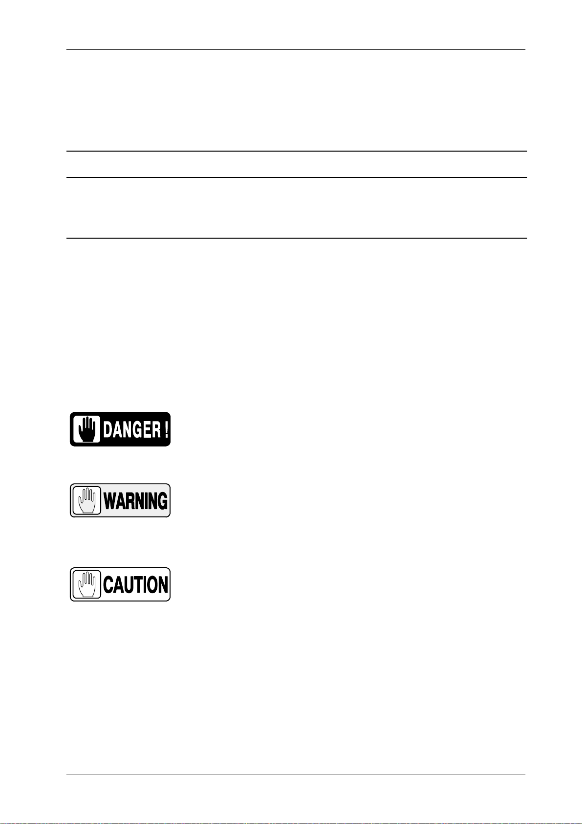
The following advisory symbols will be used throughout this manual. Their
application and meaning are described below.
DANGERS ADVISE OF CONDITIONS OR SITUATIONS THAT
IF NOT HEEDED OR AVOIDED WILL CAUSE SERIOUS
PERSONAL INJURY OR DEATH.
ADVISE OF CONDITIONS OR SITUATIONS THAT IF NOT
HEEDEDORAVOIDEDCOULDCAUSESERIOUSPERSONAL
INJURY, OR CATASTROPHIC DAMAGE OF EQUIPMENT OR
DATA.
Advise of conditions or situations that if not heeded or
avoidedcouldcausepersonalinjuryordamagetoequipment
or data.
Note .Alert readers to pertinent facts and conditions. Notes represent
information that is important to know but which do not necessarily
relate to possible injury or damage to equipment.

HF Series Generators
Installation
IN-1052R2 i
TABLE OF CONTENTS
Section Page
1 INTRODUCTION 1.........................................................
1.1 Tools and Test Equipment 1............................................
1.2 Pre-Installation Check 2...............................................
1.3 General Cautions 3...................................................
2 UNPACKING, POWER LINE CONNECTION AND CABINET INSTALLATION 5...
2.1 Control Console Installation (optional) 14.................................
3 CABLE CONNECTIONS 15..................................................
3.1 Cable Routing Inside Generator Cabinet 15...............................
3.1.1 General Cable Routing 15.......................................
3.2 High Voltage Cables Connection 17......................................
3.2.1 X-ray Tubes with Metallic Insert Envelope 17.......................
3.2.2 High Voltage Cables 18..........................................
3.3 X-ray Tube Connection 20..............................................
3.3.1 Stator Cable 20.................................................
3.3.2 Tube Selection Signals 23.......................................
3.4 Interconnection Cables 23..............................................
3.4.1 Serial Interconnection RS232 / RS422 25..........................
3.4.2 Collimator Error Signal (optional) 31...............................
3.4.3 Door Interlock Signal 31.........................................
3.4.4 Warning Light Signal 32.........................................
3.4.5 Collimator Lamp and System Locks 32............................
3.4.6 Buckys (optional) 33............................................
3.4.7 Tomo Device (optional) 33.......................................
3.4.8 Ion Chambers (optional) 34......................................

HF Series Generators
Installation
IN-1052R2
ii
Section Page
4 FINAL INSTALLATION AND CHECKS 39.....................................
4.1 HV Transformer 39....................................................
4.2 Cable Fastening and Covers 39.........................................
5 SYSTEM INTERCONNECTIONS 41...........................................
5.1 System Interconnection Signals 41.......................................
5.2 System Interconnection Maps 43........................................

HF Series Generators
Installation
IN-1052R2 1
SECTION 1 INTRODUCTION
The Installation process depends on the Generator and System configuration.
Installation must be performed in the order indicated along this document.
Perform only the sections required to install this Generator.
1.1 TOOLS AND TEST EQUIPMENT
The following hand tools and products are required for the Installation:
•Standard service engineers tool kit.
•Electric drill motor and assorted bits.
•Silicone Insulating Grease (proofing compound).
•Alcohol cleaning agent.
The following test equipment is required for Configuration and Calibration:
•Digital Multimeter.
•Non-invasive kVp Meter.
•Digital mAs Meter.
•Calculator.
•Only for AEC purposes:
GSensitometer (only for Film).
GDensitometer (only for Film).
GCopper Plates for the Collimator Filter Holder (recommended):
2 units of 1 mm thickness,
1 unit of 0.5 mm thickness,
2 units of 0.2 mm thickness,
1 unit of 0.1 mm thickness.
GAcrylic Plastic Plates can be used Instead of Copper Plates:
6 units of 5 cm. thickness,
5 units of 1cm. thickness.
GDosimeter (optionally).
•Only for Tomo purposes:
GTomophantom tool.

HF Series Generators
Installation
IN-1052R2
2
1.2 PRE-INSTALLATION CHECK
Prior to beginning installation, it is recommended to inspect the site and verify
that the X-ray room complies with Pre-installation requirements, such as:
•Incoming Line.
•Main Switch and Safety Devices.
•Conduits.
•Space Requirements.
(Refer to the “Pre-Installation” document.)

HF Series Generators
Installation
IN-1052R2 3
1.3 GENERAL CAUTIONS
MAKE SURE THAT THE MAIN STORAGE CAPACITORS OF
THE HIGH VOLTAGE INVERTER DO NOT CONTAIN ANY
RESIDUAL CHARGE. WAIT UNTIL THE LIGHT EMITTING
DIODES ON THE CHARGE-DISCHARGE MONITOR BOARDS
ARE OFF, APPROXIMATELY 3 MINUTES AFTER THE UNIT IS
TURNED OFF.
ALWAYS HAVE THE “IPM DRIVER BOARD” CONNECTED IN
THE GENERATOR PREVIOUS TO MAINS POWER IS
ACTIVATED IN IT. IF THE “IPM DRIVER BOARD” IS NOT
CONNECTED, PERMANENT DAMAGE WILL OCCUR TO
IGBTS.
TO AVOID ELECTRIC SHOCK, DO NOT TOUCH ANY
HEATSINK OF THE CIRCUIT BOARDS EVEN THE
GENERATOR IS TURNED OFF. PREVIOUS TO
DISASSEMBLE ANY BOARD, REMOVE ALL CONNECTORS
PLUGGED TO IT.
LINE POWERED GENERATOR:
THIS GENERATOR IS PERMANENTLY CONNECTED TO THE
POWER LINE, AND POWERED ON UNLESS THE SAFETY
SWITCH INSTALLED IN THE ROOM ELECTRICAL CABINET
IS OFF. WHEN THE GENERATOR IS POWERED, THE NEON
LAMP (GREEN) LOCATED ON THE TRANSFORMER 6T2
(GENERATOR CABINET) IS ON.
INTERNAL PARTS OF THE GENERATOR (ALL FUSES, LINE
CONTACTOR (6K5), INPUT TRANSFORMER (6T2), ON/OFF
RELAY (3K3) AND LF-RAC MODULE) ARE PERMANENTLY
POWERED ON THROUGH POWER LINE ALTHOUGH THE
CONTROL CONSOLE IS OFF. BE SURE THAT THE SAFETY
SWITCH IS OFF BEFORE HANDLING ANY INTERNAL PART
OF THE EQUIPMENT.


HF Series Generators
Installation
IN-1052R2
4
This page intentionally left blank.

HF Series Generators
Installation
IN-1052R2 5
SECTION 2 UNPACKING, POWER LINE CONNECTION
AND CABINET INSTALLATION
The Generator is shipped in one box to facilitate transport and installation.
Upon receipt of the X-ray unit and associated equipment, inspect all shipping
containers for signs of damage. If damage is found, immediately notify the
carrier or their respective agent.
It is recommended to install the U-Arm Positioner before
than the Generator. (Refer to the Positioner Service Manual).
1. Open the shipping box. Take out the Control Console (if provided),
Interconnection Cables, CabinetCoverandotherfurnishedparts.Donot
discard any packing material such as envelopes, boxes or bags until all
parts are accounted for as listed on the packing list.
2. Remove the packing material from the pallet.
3. Remove the Generator Cabinet from the shipping pallet, placing it near
its chosen room position. This operation requires at least two people.
4. When the equipment is unpacked, verify that all items on the customer
order are present, and the hardware and internal wiring is secure.
5. Check the part numbers / serial numbers of each component with its
identification labels, and inspect all pieces for visible damage. If any
damaged parts are found, repair or order replacements to prevent
unnecessary delay in installation.
Illustration 2-1
Compact Generators

HF Series Generators
Installation
IN-1052R2
6
6. Previous to install the Generator Cabinet on the upper side of the
Positioner Control Box, it is recommended to perform the Power Line
connection.
KEEP IN MIND THE GENERAL CAUTIONS FOR LINE
POWERED GENERATORS INDICATED IN SECTION 1.3.
DO NOT POWER ON THE GENERATOR UNTIL
SPECIFICALLY INSTRUCTED IN THIS SERVICE MANUAL.
7. The power supply line should conform with the Generator model defined
in the “Pre-Installation” document. Wire sizes indicated in this document
arerelativetothepowersupply lineandwirelength. Verifythat thepower
line voltage and phase of the Generator coincides with the one for Room
Electrical Cabinet.
8. Route the Power Line Cables and the Ground wires to the Input Line
FusesandGroundStudsintheCabinetFrame(GroundStuds areabove
the input fuses or close to the right side of the HV Transformer). These
cables can be secured to the Fastening Bar of the Cabinet and routed
internally along the rear side of the Cabinet (always apply Local Codes
for cable routing). (Refer to Illustration 2-2.)
Illustration 2-2
Cable Routing in the Line Powered Generator
Power Line Cables
Input Line Fuses
Fastening Bar
Ground Terminals
Input Transformer 6T2
Andere Handbücher für HF Series
1
Inhaltsverzeichnis
Andere TXR Tragbarer Generator Handbücher