
Vante 4105 Bedienungsanleitung

Doc. No. 41050810-01 Rev D
INSTRUCTION
MANUAL
MODEL 4105
Hand-Held Sealing Head

ii
This page intentionally left blank

5/10 Vante®iii
Vante®
3480 E. Britannia Dr., Suite 120
Tucson, AZ 85706 USA
Telephone (520) 881-6555
Fax (520) 323-9055
Toll Free (877) 565-5557
Part No. 41050810-01 Rev. D

iv
This page intentionally left blank

v
Preliminary Information
Document Scope
This manual is intended as a guide for the operation, care and maintenance of the
Vante®Model 4105 Hand-Held Sealing Head. The information contained herein
is based upon technical data that have been validated by Vante®and is believed to
be appropriate for the intended use of the product.
Intended Audience
This manual is intended for use by personnel with technical skills and a thorough
understanding of the products, procedures, and safety requirements for processing
and handling of biopharmaceutical products.
Application
The Model 4105 Hand Held Sealing Head is part of a system and cannot be used
independently. When used in conjunction with a Vante®radio frequency (RF)
Power Source, it is the instrument used to make seals on tubing made of
RF-reactive thermoplastic materials typically used in biopharmaceutical
manufacturing. Tubing utilized in the handling of biopharmaceutical products are
typically made from thermoplastic vinyl, namely polyvinylchloride, (PVC) or
ethylene vinyl acetate (EVA), and it is this application for which this product is
specifically intended.
Exclusions and Limits of Liability
Vante®makes no warranties, expressed or implied, and assumes no liability in
connection with any use of this information. If the Sealing Head or its related
procedures are used for purposes other than those stipulated herein, validation of
the specific application should be obtained, otherwise Vante®assumes no liability
or obligation nor guarantees product performance. Personnel using the Sealing
Head do so at their own discretion and risk.
vi
Proprietary Information
All rights are reserved. Copying of the protected designs associated with the
Model 4105 Sealing Head is strictly prohibited without the prior written consent
of Vante®.
User Alerts
Throughout this document WARNINGS, CAUTIONS and NOTES are employed
to notify the user of important and/or critical information.
WARNING: A Warning indicates a condition or procedure that could result in
improper tube sealing or possible injury to the user. A Warning is
enclosed with a bold-line box.
CAUTION: A Caution indicates a condition or procedure that could result in
damage to the unit. A Caution is enclosed with a single-line box.
NOTE: A Note indicates important and/or useful information.
Safety Symbols
Caution, risk of electric shock
Caution
Protective Earth (P.E.)
Fuse
|On
Off
WEEE –Indicates electronic equipment requiring proper recycling
(EU only)
CE Mark Information
For inquires related to the CE marking of this product, please contact Vante®at
3480 E. Britannia Dr, Suite 120, Tucson, Arizona 85706 U.S.A., 520-881-6555,
520-323-9055 (fax).

vii
Table of Contents
Preliminary Information...........................................................................................v
Document Scope.............................................................................................v
Intended Audience ..........................................................................................v
Application......................................................................................................v
Exclusions and Limits of Liability..................................................................v
Proprietary Information................................................................................. vi
User Alerts .................................................................................................... vi
Safety Symbols.............................................................................................. vi
CE Mark Information.................................................................................... vi
Table of Contents......................................................................................... vii
Table of Figures..........................................................................................viii
Table of Tables ........................................................................................... viii
1. Sealing Head Description...................................................................................1
1.1 Product Overview ..................................................................................1
1.2 Theory of Operation...............................................................................1
1.3 Component Identification ......................................................................1
1.4 Environment...........................................................................................3
2. Sealing Head Operation .....................................................................................5
2.1 Setup ......................................................................................................5
2.2 Splash Guard Installation.......................................................................5
2.3 Sealing Procedure ..................................................................................7
2.4 Seal Spacing.........................................................................................10
3. Cleaning the Sealing Head...............................................................................11
3.1 Topical Cleaning of the Sealing Region ..............................................12
3.2 Disassembly of the Sealing Head.........................................................15
3.3 General Cleaning of the Sealing Head.................................................18
3.4 Reassembly of the Sealing Head..........................................................18
4. Repair...............................................................................................................23
4.1 Troubleshooting...................................................................................23
4.2 Spring Replacement.............................................................................24
4.3 Returning a Unit for Repair .................................................................25
5. Radio Frequency System Safety Considerations..............................................27
5.1 General Information.............................................................................27
5.2 RF Effects On Human Tissue ..............................................................27
5.3 RF Effects On Pacemakers ..................................................................27
5.4 Electrical Safety...................................................................................27
5.5 RF Effects On Electronic Equipment...................................................27
5.6 RF Effects In Potentially Explosive Atmospheres...............................28

viii
Table of Figures
Figure 1.1 Model 4105 Hand Held Sealing Head...................................................2
Figure 2.1 Tab and Sides A & B of Splash Guard..................................................5
Figure 2.2 Splash Guard Tab ..................................................................................6
Figure 2.3 Final Attachment of Splash Guard ........................................................6
Figure 2.4 Correct Technique for Holding the Sealing Head .................................7
Figure 2.5 Incorrect Technique for Holding the Sealing Head...............................8
Figure 2.6 Maintaining Compression During the Entire Sealing Process ..............8
Figure 2.7 Releasing the Sealing Head Lever at Seal Completion .........................9
Figure 3.1 Incorrect Cleaning Technique..............................................................11
Figure 3.2 Correct Lever/Sealing Body Gap.........................................................12
Figure 3.3 Cleaning the Sealing Region ...............................................................13
Figure 3.4 Drying the Sealing Region...................................................................13
Figure 3.5 Cleaning Ground and RF Jaw Surfaces...............................................14
Figure 3.6 Drying Ground and RF Jaw Surfaces ..................................................14
Figure 3.7 Releasing Spring Tension in Sealing Head .........................................16
Figure 3.8 Removing the Lever and Ground Jaw.................................................17
Figure 3.9 Sealing Head Components...................................................................17
Figure 3.10 Cleaning Individual Sealing Head Components................................18
Figure 3.11 Installation of Ground Jaw onto RF Jaw/Tube Assembly.................19
Figure 3.12 Installation of Lever on to Sealing Head...........................................19
Figure 3.13 Installation of Lever into Pivot Slots.................................................20
Figure 3.14 Final Assembly of Sealing Head .......................................................21
Table of Tables
Table 1.1 Sealing Head Component Functions................................................2

Vante®Model 4105
1
1. Sealing Head Description
1.1 Product Overview
The Vante®Model 4105 Hand-Held Sealing Head (“the Sealing Head”) is part of a
system which employs radio frequency (RF) to make uniform, quality seals on a variety
of tubing sizes. A Vante®Power Source (Model 4380 or 4600) provides RF power to the
Sealing Head and controls RF power and sealing time. The manually-activated Sealing
Head forms a seal with its jaws in such a way as to make segment separation easy and
uniform. The Sealing Head is equipped with a splash guard for operator protection from
inadvertent contact with biopharmaceutical products in the unlikely event of tubing
rupture.
1.2 Theory of Operation
The physical properties of PVC plastic tubing (and other RF-reactive thermoplastic
materials) cause it to dielectrically heat at a molecular level in the presence of RF energy.
This energy causes the plastic to soften due to the friction of the vibrating molecules. In
this softened condition, the plastic becomes weldable because the molecules are free to
intermingle under the application of external forces, such as compression. If allowed to
cool while the forces are applied, the material will be permanently reshaped.
The Sealing Head receives a controlled amount of RF energy from the generator while
mechanically compressing the tubing across its diameter during the dielectric sealing and
forming process. When the energy is removed and the tubing is allowed to cool under
compression, a permanent seal is produced.
1.3 Component Identification
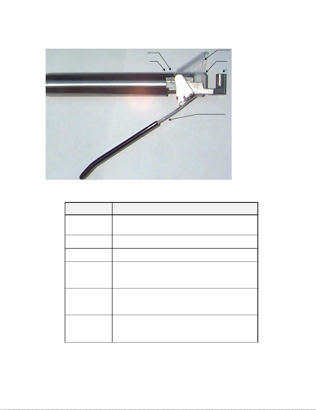
Table 1.1 indicates the function of each component included with the Sealing Head.
Vante®Model 4105
2
Sealing Indicator Light
Serial Number
Splash Guard
RF Jaw
Ground Jaw
Lever
Assembly
Figure 1.1 Model 4105 Hand Held Sealing Head
Component
Function
Lever Assembly
Compresses the tubing between the jaws and activates the
sealing process.
RF Jaw
Compresses tubing with ground jaw while applying RF.
Ground Jaw
Grounds RF as it is applied and molds tubing.
Splash Guard
Attached to the lever of the Model 4105. Protects the
operator from accidental exposure to biopharmaceutical
products in the unlikely event of a tubing rupture.
Sealing Indicator
Light
Light on Sealing Head that indicates duration of RF power.
The Sealing Head jaws must remain closed until two seconds
after the indicator light turns completely off.
Serial Number
Indicates the serial number. Please make note of this
number when calling the Vante®Customer Service
Department.
Table 1.1 Sealing Head Component Functions
Inhaltsverzeichnis
Andere Vante Lebensmittelkonservierung Handbücher


