Vecima TRI2525B Betriebsanleitung

TRI2525B
2.5 – 2.6 GHZ SERIES
BROADBAND WIRELESS TRANSCEIVER
INSTALLATION AND OPERATION GUIDE

tri2525b_ml_03_sd Approved: G.V. ii
Vecima Networks Inc.
Document: tri2525b_ml_03_sd
Approved: G.V.
Proprietary to Vecima Networks Inc.
All rights reserved.
No part of this publication may by reproduced in any form or by any means or used to make any derivative work (such as translation, transformation or
adaptation) without written permission from Vecima Networks Inc.
Vecima Networks Inc. reserves the right to revise this publication and to make changes in content from time to time without obligation on the part of
Vecima Networks Inc. to provide notification of such revision or change.
Vecima Networks Inc. provides this guide without warranty of any kind, either implied or expressed, including, but not limited to, the implied warranties of
merchantability and fitness for a particular purpose. Vecima Networks Inc. may make improvements or changes in the product(s) described in this
manual at any time.
Specifications subject to change without notice — Printed in Canada

tri2525b_ml_03_sd Approved: G.V. iii
Vecima Networks Inc.
Thank you for purchasing this product from Vecima Networks!
Vecima Networks is a leading technology design center and provides
innovative solutions for the ongoing video, voice and data delivery revolution.
Since 1988, our design powerhouse has created custom RF and digital products for technology
leaders such as AT&T, Cisco Systems, Cogeco, Comcast and Cox Communications. All Vecima
Networks products benefit from this ground-breaking expertise.
Vecima Networks designs and manufactures:
z256 QAM Upconverters zDigital Video Modulators zAgile CATV Modulators
zFrequency Translators zSpread Spectrum Devices zMMDS Transceivers
zOff-air/CATV Demodulators zWireless Cable MMDS zWireless Cable LMDS
zEdge Devices zVideo On Demand Products and more!
For additional product or corporate information, please contact Vecima Networks at:
Vecima Networks Inc.
150 Cardinal Place
Saskatoon, SK Canada S7L 6H7
Tel: (306) 955-7075
Fax: (306) 955-9919
Web: www.vecimanetworks.com

tri2525b_ml_03_sd Approved: G.V. iv
Vecima Networks Inc.
SAFETY PRECAUTIONS
1. Before installing and operating this equipment, read all Safety, Installation and Operating sections. Retain this
manual for future reference.
2. Follow all instructions — Failure to do so may result in damage to the unit or severe personal injury.
3. The user should not attempt servicing. There are no user serviceable parts inside. Refer all servicing to factory
qualified personnel.
4. Shock Hazard — An electrical shock hazard exists when the chassis cover is removed as is required to set
internal controls. Always disconnect power from the unit before removing the cover.
5. Cleaning — Do not use liquid or aerosol cleaners. Use a damp cloth for cleaning.
Warning Do not work on the system or connect or disconnect cables during periods of lightning activity.
LES PRÉCAUTIONS DE SÉCURITÉ
1. Avant d'installer ou d'opérer cet équipement, lisez, toutes les sections de sécurités, d'installations et d'opérations.
Gardez ce manuel comme source de référence.
2. Suivez toutes instructions - si non, vous risquez d'endommager la machine ou de vous blesser sérieusement.
3. N'essayez, pas de réparer cet équipement vous même. Référez toutes revisions nécessaire au personnel
qualifié de la manufacture.
4. Risque de choc - Il y a un risque de décharge électrique qui existe quand la couverture du châssis est enlevée,
comme est nécessaire pour ajuster les contrôlcs internes. Il faut toujours couper l'électricité avant d'enlever le
couvercle pour faire aucun ajustage.
5. Le nettoyage - n'utilisez pas de nettoyeurs aérosols ou liquides. Utilisez un tissu humide pour nettoyer.
Attention Ne pas travailler sur le système ni brancher ou débrancher les câbles pendant un orage du foudre.

tri2525b_ml_03_sd Approved: G.V. v
Vecima Networks Inc.
INDEX
1.0 GENERAL INFORMATION .......................................................................................................................... 7
1.1 Functional Overview ................................................................................................................................................... 7
1.2 Module Features .......................................................................................................................................................... 7
1.3 Specifications................................................................................................................................................................ 8
2.0 INSTALLATION ............................................................................................................................................. 9
2.1 Unpacking the Unit...................................................................................................................................................... 9
2.2 Mounting the Unit ....................................................................................................................................................... 9
2.3 Connection to the Power Inserter and Cable Modem ............................................................................................ 13
2.4 Waterproofing Connections...................................................................................................................................... 14
3.0 ALIGNING THE ANTENNA ....................................................................................................................... 16
3.1 Preparation for Tuning............................................................................................................................................. 16
3.2 Signal Strength and Alignment ................................................................................................................................ 16
3.3 Resetting the Beeper .................................................................................................................................................. 16
4.0 WARRANTY AND SERVICE POLICIES ................................................................................................... 17
4.1 Warranty Statement.................................................................................................................................................. 17
4.2 Service Policies: How to Return an Item for Service: ............................................................................................ 17
4.3 Repair Charges and Warranty Exemptions............................................................................................................ 18

tri2525b_ml_03_sd Approved: G.V. vi
Vecima Networks Inc.

tri2525b_ml_03_sd Approved: G.V. 7
Vecima Networks Inc.
1.0 GENERAL INFORMATION
1.1 Functional Overview
The Vecima Networks TRI2525B is an outdoor RF transceiver for use in broadband wireless systems.
The TRI2525B combines a low noise downconverter, high power upconverter, antenna and high
rejection duplexer to offer a fully integrated solution for 3.5 GHz subscriber terminals. The TRI2525B
integrated subscriber transceiver serves to frequency translate and amplify the upstream and
downstream signals to the appropriate intermediate frequencies for use by the indoor DOCSIS modem.
The TRI2525B and antenna are situated outdoors and connected to a cable modem indoors by a low
cost 75 ohm cable (i.e. RG-59, RG-6 or similar). A single RF F-connector on the weatherproofed
enclosure provides the interface to the transmit/receive antenna for rapid installation.
1.2 Module Features
•High Output Power: Up to +39 dBm EIRP with QPSK
•Automatic transmit RF mute when modem is not transmitting
•Low Noise: < 7 dB typical
•Temperature compensation to guarantee specifications over full operating temperature range
•All local oscillators are frequency synthesized and locked to a common internal high stability reference
•Integrated planar antenna (15°beamwidth, 18 dBi gain)
•High reliability, state-of-the-art design using microstrip, MMIC and surface mount technology
•Conservative component derating and 100% burn in help ensure reliable operation
•Fully weatherized unit, suitable for outdoor mounting
•Audible installation alignment beeper; to facilitate customer self install

tri2525b_ml_03_sd Approved: G.V. 8
Vecima Networks Inc.
1.3 Specifications
Subscriber Transceiver Specifications
TRANSMIT SPECIFICATIONS
IF Input Frequency 18 to 42 MHz*
Automatic Mute Threshold Level -47 dBm
Automatic Mute Response Time < 1.2 microseconds
RF Frequency Range 2500 to 2524 MHz*
Rated Output Power 16QAM: +37 dBm; QPSK: +39dBm
Integrated Gain 33 ±1dB
Gain Flatness ±1dB peak to peak
Gain Stability ±2 dB over temperature
Spectral Mask FCC CFR 47 Part 21 / Industry Canada RSS193
Phase Noise <-90 dBc / Hz at 10 kHz
<-45 dBc integrated over 10 kHz to 2.5 MHz
Frequency Setting and Stability ±5.0 kHz
Frequency Stability over 10 years ±10 kHz
RECEIVE SPECIFICATIONS
RF Frequency Range 2566 to 2596 MHz*
Frequency Response (any 6 MHz band) ±0.5 dB
IF Output Frequency Range 534 to 564 MHz*
Noise Figure 5.5dB typical <7 dB max including narrowband duplexer
loss
Integrated Gain 44 ±1dB
Input Third Order Intercept Point -7 dBm at LNA input
Interference Sensitivity As per ETSI EN 301 021 section 5.4.4.3 when used in
conjunction with
DOCSIS certified modems
Phase Noise <-90 dBc / Hz at 10 kHz
<-45 dBc integrated over 10 kHz at 2.5 MHz
Frequency Setting and Stability ±5.0 kHz
Frequency Stability over 10 years ±10 kHz
GENERAL
IF Connector F female, 75 ohms
IF Return Loss 10 dB
Power Requirement +21 to +28 VDC
Power Consumption 11 W maximum
Operating Temperature Range -40 to +55°C ambient full specifications
Antenna Gain 16 dBi minimum
Antenna Beamwidth 15°typical
Antenna Compliance RSS193
Spurious Emissions RSS193
EMC Compliance RSS193
Dimensions 12” x 12” x 2.5” (305mm x 305mm x 64 mm) maximum
Weight 7 lbs. (3.2 kg)
Specifications subject to change without notice.

tri2525b_ml_03_sd Approved: G.V. 9
Vecima Networks Inc.
2.0 INSTALLATION
2.1 Unpacking the Unit
Carefully remove the equipment from its packing material and set it on a solid surface, such as a table
or desk. If it appears damaged in any way, notify the carrier, and keep all packing materials for
inspection by the carrier’s agent.
2.2 Mounting the Unit
The following hardware is included in the box for mounting the brackets to the pole:
•1 L-bracket (taped to one of the foam pieces inside the box)
•1 pole catch
•1 V-bolt
•4 #10-32 flange locknuts for connecting L-bracket to cover
•2 ¼ - 20 flange locknuts for connecting V-bolt and pole catch to the pole
The TRI2525B was designed for mounting on a pole with a diameter of 1.0” to 1.75”. Please ensure
that the pole used is attached securely to the building or other mounting location.
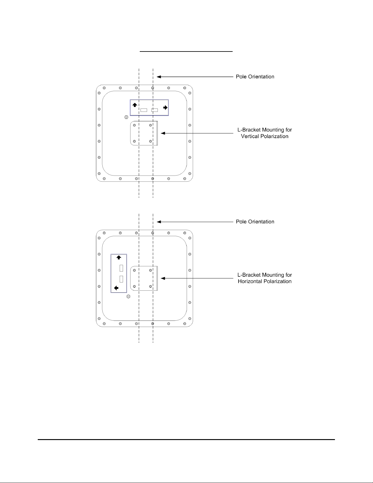
Step 1 – Attach L-Bracket to TRI2525B
Before the unit can be attached to the pole, the L-bracket must be attached in the correct orientation
according to the polarization required for the particular customer installation. Diagram 2.2A shows the
orientation of the bracket relative to the cover for both horizontal and vertical polarization.
The active or desired polarization is the one in which the arrow points up. For example, when the
TRI2525B is mounted on the pole, if the arrow pointing up on the back of the TRI2525B says “Horizontal
Polarization” then the horizontal polarization is the active polarization. When the TRI2525B is mounted
on the pole, if the arrow pointing up on the back of the TRI2525B says “Vertical Polarization”, the
vertical polarization is the active polarization
Secure the L-bracket to the cover using the #10-32 locknuts.
tri2525b_ml_03_sd Approved: G.V. 10
Vecima Networks Inc.
DIAGRAM 2.2A:L-BRACKET ORIENTATION
Once the L-bracket is in place, the unit can be mounted to the pole. The pole catch, V-bolt and L-
bracket are oriented as shown in Diagram 2.2B.
Inhaltsverzeichnis
Andere Vecima Transceiver Handbücher


