Ventrac 2100C Bedienungsanleitung

09.10146 Rev. 00

If you need to contact an authorized Ventrac dealer for information on servicing your product,
always provide the product model and serial numbers.
Please ll in the following information for future reference. See the picture(s) below to nd the
location of the identication numbers. Record them in the spaces provided.
Date of Purchase: __________________________________________________________________
Dealer:___________________________________________________________________________
Dealer Address:____________________________________________________________________
____________________________________________________________________
Dealer Phone Number: ______________________________________________________________
Dealer Fax Number: ________________________________________________________________
Model # (A): ___________________________
Serial # (B): ____________________________
Afx Part/Serial Number label here.
Engine Serial # (C) _________________________
Venture Products Inc. reserves the right to make changes
in design or specications without obligation to make like
changes on previously manufactured products.
B
A
C

TABLE OF CONTENTS
3
Product Description................................................................................................................................6
Why Do I Need an Operator’s Manual? .................................................................................................6
Using Your Manual .................................................................................................................................7
Manual Glossary ....................................................................................................................................7
Safety Decals.........................................................................................................................................8
General Safety Procedures.................................................................................................................. 11
Training Required................................................................................................................................. 11
Personal Protective Equipment Requirements .................................................................................... 11
Operation Safety .................................................................................................................................. 11
Preventing Accidents............................................................................................................................12
Keep Riders O....................................................................................................................................12
Operating On Slopes............................................................................................................................13
Roadway Safety...................................................................................................................................13
Truck Or Trailer Transport ....................................................................................................................13
Maintenance.........................................................................................................................................14
Fuel Safety...........................................................................................................................................14
Hydraulic Safety ...................................................................................................................................15
Operator Safety Interlock System ........................................................................................................16
2100 Safety Procedures.......................................................................................................................16
Testing the Safety Interlock System .....................................................................................................17
Operational Control Locations..............................................................................................................18
Cluster Gauge (A) ................................................................................................................................19
Headlight Switch (B).............................................................................................................................19
Ignition Switch (C) ................................................................................................................................19
USB Receptacle (D).............................................................................................................................19
Drive Control Handles (E) ....................................................................................................................19
Hydraulic Control Lever (F) ..................................................................................................................20
Parking Brake (G) ................................................................................................................................20
Choke Handle (H) ................................................................................................................................20
Throttle Lever (I)...................................................................................................................................20
Latch Handle Lock (J) ..........................................................................................................................20
Attachment Latch Handle (K)...............................................................................................................20
Auxiliary Hydraulic Quick Couplers (L).................................................................................................20
Circuit Breaker & Battery Disconnect (M) ............................................................................................20
Fuel Shut-o Valve (N) .........................................................................................................................21
Rear Work Light Switch (AA) ...............................................................................................................21
Power Take O (PTO) Switch (BB) ......................................................................................................21
12 Volt Front Switch & 4-Pin Outlet (CC & EE) ....................................................................................21
Brine Pump Switch (DD) ......................................................................................................................21
Weight Transfer Selector Handle (FF) .................................................................................................21
Attachment Belt Tension Spring (GG) ..................................................................................................21

TABLE OF CONTENTS
Daily Inspection....................................................................................................................................22
Starting the Engine...............................................................................................................................22
Forward and Reverse...........................................................................................................................22
Turning (Left, Right, & Turn in Place)...................................................................................................23
Stopping the Power Unit ......................................................................................................................23
Shutting O the Engine ........................................................................................................................23
Attaching ..............................................................................................................................................24
Detaching.............................................................................................................................................25
Operating Attachments.........................................................................................................................25
Front Hitch............................................................................................................................................25
Front Auxiliary Couplers.......................................................................................................................25
Weight Transfer (Optional Accessory)..................................................................................................26
Front 12 Volt 4-Pin Outlet (Optional Accessory)...................................................................................26
Towing Or Pushing the Power Unit ......................................................................................................26
Service and General Maintenance.......................................................................................................27
Cleaning and Appearance Care ...........................................................................................................27
Service Access Points..........................................................................................................................28
Lubrication Locations ...........................................................................................................................28
Checking Hydraulic Oil Level ...............................................................................................................29
Changing Hydraulic Oil & Filters ..........................................................................................................30
Servicing Hydraulic Oil Cooler .............................................................................................................31
Checking Engine Oil Level...................................................................................................................31
Changing Engine Oil and Filter ............................................................................................................32
Air Filter Service and Replacement......................................................................................................33
Filling the Fuel Tank .............................................................................................................................33
Changing the Fuel Filter.......................................................................................................................34
Cleaning Engine Compartment & Engine ............................................................................................34
Servicing the Battery............................................................................................................................34
Removing the Battery...........................................................................................................................35
Installing the Battery.............................................................................................................................35
Cleaning the Battery and Terminals .....................................................................................................35
Charging the Battery ............................................................................................................................35
Jump Starting Procedure .....................................................................................................................36
Replacing Fuses ..................................................................................................................................36
Replacing the Headlights and Work Lights ..........................................................................................37
Belt Inspection......................................................................................................................................37
Pump Drive Belt Replacement.............................................................................................................37
PTO Drive Belt Replacement...............................................................................................................38
Wheel Removal & Installation ..............................................................................................................38
Tire Pressure........................................................................................................................................38
Parking Brake Adjustment....................................................................................................................39
Parking Brake Switch Adjustment ........................................................................................................39
Operator Presence Switch Adjustment ................................................................................................40

TABLE OF CONTENTS
Drive Control Handle Adjustment .........................................................................................................40
Neutral Arm Adjustment .......................................................................................................................41
Neutral Switch Adjustment ...................................................................................................................41
Storage.................................................................................................................................................42
Maintenance Schedule.........................................................................................................................43
Maintenance Checklist.........................................................................................................................44
Ventrac Maintenance Log ....................................................................................................................45
Wiring Diagram Reference Key............................................................................................................47
Wiring Harness Diagram ......................................................................................................................48
Wiring Diagram - Optional 30.0219 4-Pin Female Socket & 30.0218 4-Pin Male Plug........................50
Engine..................................................................................................................................................51
Electrical...............................................................................................................................................52
Hydraulic ..............................................................................................................................................52
Power Unit............................................................................................................................................53
Engine..................................................................................................................................................54
Electrical...............................................................................................................................................54
Power Train ..........................................................................................................................................54
Controls & Instrument Panel ................................................................................................................54
Other Features.....................................................................................................................................54
Dimensions ..........................................................................................................................................54
Fluid Capacities & Specications.........................................................................................................55
Belt Chart .............................................................................................................................................55

The Ventrac 2100 SSV is a dedicated sidewalk snow vehicle with a 4x4 skid steer drive system.
The 34 inch (86.4 cm) working width of the Ventrac 2100 allows access to narrow sidewalks and transi-
tional areas, reducing the need for hand labor.
The Ventrac 2100 is designed with a full arsenal of snow removal attachments and de-icing options. A self
aligning front hitch allows quick and easy mounting of snow removal attachments.
An optional PTO kit is available for powered attachments.
This manual has been created to help you gain the important knowledge of what is needed to safely
operate, maintain, and service your machine. It is divided into sections for convenient reference of the
appropriate section.
You must read and understand the operator’s manual for each piece of Ventrac equipment you own. Read-
ing the operator’s manual will help you become familiar with each specic piece of equipment. Under-
standing the operator’s manual will help you, as well as others, avoid personal injury and/or damage to the
equipment. Keep this manual with the machine at all times. The manual should remain with the machine
even if it is sold. If this manual becomes damaged or unreadable, it should be replaced immediately. Con-
tact your local Ventrac dealer for a replacement.
When using a Ventrac attachment, be sure to read and follow the safety and operating instructions of both
the power unit and the attachment being used to ensure the safest operation possible.
The information in this manual provides the operator with the safest procedures to operate the machine
while getting the maximum use out of the unit. Failure to follow the safety precautions listed in this manual
may result in personal injury and/or damage to the equipment.
Venture Products Inc. is pleased to provide you with your new
Ventrac power unit! We hope that Ventrac equipment will
provide you with a ONE Tractor Solution.
Listed below are just some of the items that can provide you
versatility as you use your 2100 power unit. Please visit our
website, or contact your authorized Ventrac dealer for a com-
plete list of items available for your new power unit.
Attachments
Accessories
Blade - 42” 39.65110 NA130 Drop Spreader 70.6001
Broom - 38” 39.65100 NB200 Brine System 70.6002
PTO Kit 70.6003
Weight Transfer Kit 70.6004
Rear Work Light Kit 70.6005
12 Volt Front Kit 70.6006
Storage Basket Kit 70.6010
INTRODUCTION
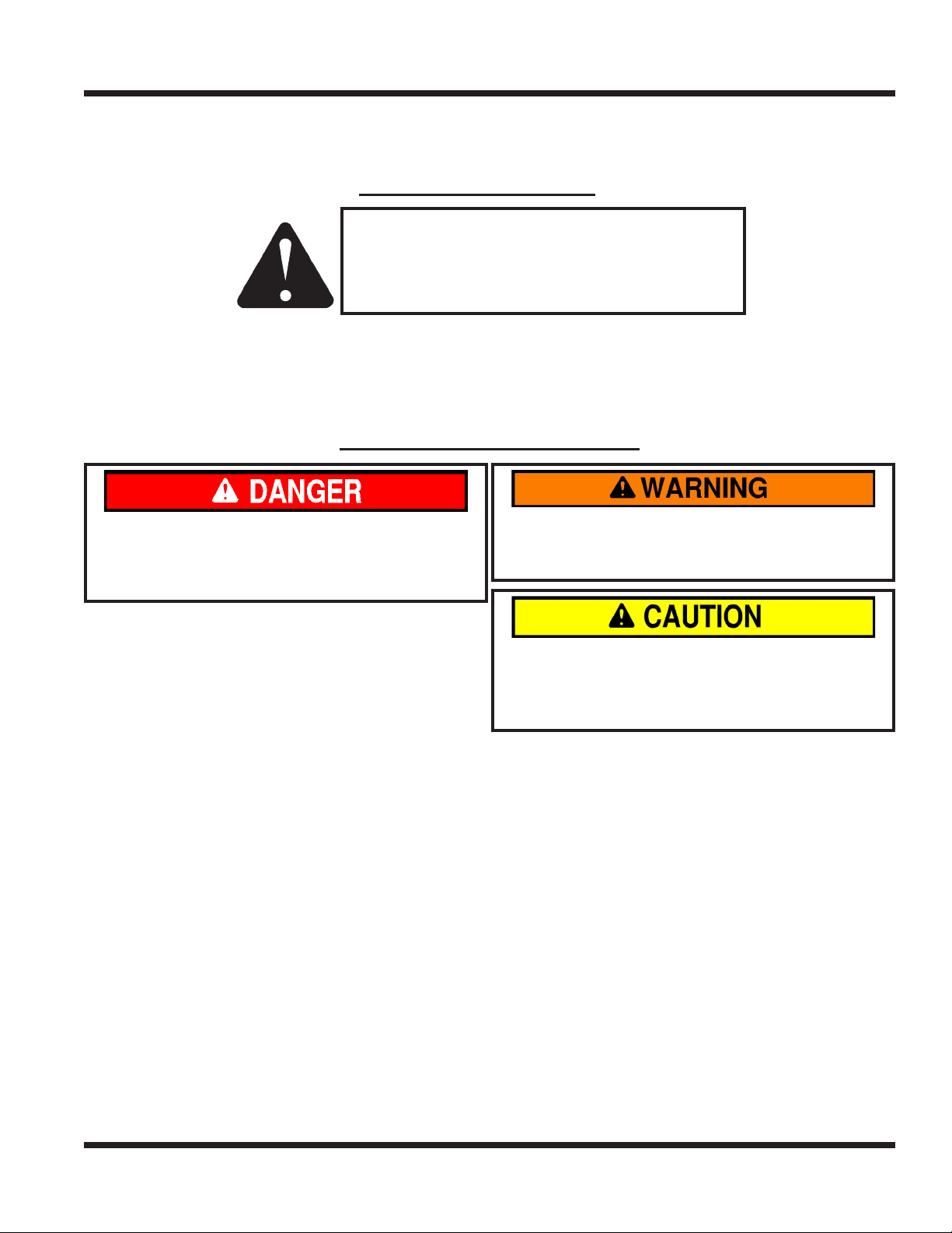
Throughout this manual, you will encounter special messages and symbols that identify potential safety
concerns to help you as well as others avoid personal injury or damage to the equipment.
This symbol identies potential health and
safety hazards. It marks safety precautions.
Your safety and the safety of others is involved.
There are three signal words that describe the level of safety concern: Danger, Warning, and Caution.
Safety should always be the #1 priority when working on or operating equipment. Accidents are more likely
to occur when proper operating procedures are not followed or inexperienced operators are involved.
Note: Right-Hand and Left-Hand orientations may be referred to at dierent places throughout this manual.
Right-Hand and Left-Hand is determined as if facing forward from the operator station.
Indicates a potentially hazardous situation
which, if not avoided, could result in death or
serious injury.
Indicates an imminently hazardous situation
which, if not avoided, will result in death or
serious injury. This signal word is limited to the
most extreme cases.
Indicates a potentially hazardous situation
which, if not avoided, may result in minor or
moderate injury and/or property damage. It may
also be used to alert against unsafe practices.
A Ventrac tractor or other Ventrac engine powered device that may be operated by itself or
with an attachment or accessory.
A piece of Ventrac equipment that requires a Power Unit for operation.
A device that attaches to a Power Unit or Attachment to extend its capabilities.
Describes any “Attachment” or “Accessory” that is used in conjunction with a power unit.

The following safety decals must be maintained on your Ventrac 2100 power unit.
Keep all safety decals legible. Remove all grease, dirt, and debris from safety decals and instructional
labels. If any decals are faded, illegible, or missing, contact your dealer promptly for replacements.
When new components are installed, be sure that current safety decals are axed to the replacement
components.
A
C
E
C
C
B
D
B
C

SAFETY
1. WARNING: Read operator’s manual.
2. Wear personal protective gear, such as eye protection, boots, ear protection, and warm clothing suitable for weather conditions.
3. Operators must receive training prior to operating the machine.
4. Do not operate with shields or guards removed.
5. WARNING: Read slope operation instructions. Slow down when operating on slopes.
6. WARNING: Keep a safe distance from the edge of drop-os, curbs, ditches, etc. The machine could roll over if a wheel drops over the edge or if
the edge caves in.
7. Do not carry passengers. Stop the machine if someone enters the work area.
8. Do not operate while under the inuence of drugs or alcohol.
9. WARNING: Hydraulic uid is under high pressure and can penetrate skin, causing injury. Keep hands, face, and body away from pinholes or
nozzles that eject hydraulic uid under high pressure.
10. When towing or pushing the power unit, the drive pumps must be disengaged by opening the bypass valve on both pumps or damage to the
hydraulic system will result.
1. Hot surface hazard - Hot surfaces can cause severe
burns. Allow engine, exhaust components, and sur-
rounding surfaces to cool before servicing.
A
2 3 4
5 6 7 8 9 10
1
C
1
1. Cutting or crushing hazard - Stay away from
moving parts.
B
1

SAFETY
A Warning, Operator Safety 00.0437 1
B Warning - Pinch Point 00.0218 2
C Warning, Hot Surface 00.0374 4
D Warning, Battery 00.0366 1
E Warning, Gasoline Only 00.0457 1
D
1
2
3
4
5
E
1
2
3
1. DANGER: Explosion / re hazard.
2. Keep away from re, sparks, and pilot lights
when refueling or storing machine and fuel.
3. Smoking is prohibited.
1. DANGER: Battery acid is caustic and can cause chemical burns. Keep by-
standers a safe distance from the battery.
2. Wear eye protection, such as goggles or a face shield, when checking or
servicing batteries.
3. Wear appropriate protective gear, such as rubber gloves and an apron, when
checking or servicing batteries.
4. Do not expose batteries to arc, sparks, or open ames. Do not use smoking
materials near batteries.
5. Explosion hazard - batteries produce ammable and explosive gases.
Inhaltsverzeichnis
Andere Ventrac Nutzfahrzeug Handbücher


