Ventrac VR300 Bedienungsanleitung

REVISED 02-03-20
09.10040
VENTRAC
VR300
OWNER/OPERATOR’S
MANUAL & PARTS LIST
Venture Products Inc. Orrville, OH

ii
TO THE OWNER
Venture Products Inc. reserves the right to make changes
in design or specifications without obligation to make like
changes on previously manufactured products.
Orrville, OH
www.ventrac.com
Model # (A): _______________________
Serial # (B): ________________________
Affix Part/Serial Number label here
Product Identification
If you need to contact an Authorized Ventrac Dealer for information on servicing your product,
always provide the Product Model and Serial numbers.
Please fill in the following information for future reference. See picture below to find the
location of the identification number. Record them in the spaces provided below.
Date of Purchase: Month _________________ Day ___________ Year ___________________
Dealer: _______________________________________________________________________
Dealer Address: ________________________________________________________________
________________________________________________________________
Dealer Phone Number: __________________________________________________________
Dealer FAX Number: ____________________________________________________________

TABLE OF CONTENTS
iii
INTRODUCTION SECTION A
Description & Specifications ................................A-1
SAFETY SECTION B
Safety Symbols .......................................B-1
Decals ...........................................B-2
Decal Locations.......................................B-3
General Safety Procedures.................................B-4
Safety Operation & Techniques...............................B-5
OPERATION SECTION C
Controls ........................................C-1 & 2
Pre-start Checklist .....................................C-3
Operator Compartment Entry................................C-3
Starting the Engine / Safety Tips / Operating Instructions .................C-4
MAINTENANCE/ADJUSTMENTS SECTION D
Precautions / General Maintenance ............................D-1
Maintenance Schedule ...................................D-2
Oils / Fuel Tank .......................................D-3
Tires / Parking Brake / Drive Belt Adjustments .......................D-4
Drive Chain / Neutral Safety Switch / Ground Clearance Adjustments...........D-5
Electrical Schematic ....................................D-6
PARTS & ILLUSTRATED DRAWINGS SECTION E
Chair Compartment...................................E-1 & 2
Tailgate Mechanism ..................................E-3 & 4
Brake Mechanism ...................................E-5 & 6
Pump Controls .....................................E-7 & 8
Drive Wheel ......................................E-9 & 10
Engine ........................................E-11 & 12
Handle Bar & Controls ................................E-13 & 14
Coast Lever & Electrical Parts ............................E-15 & 16
Shields & Battery ..................................E-17 & 18
OPTIONS
Gun Rack ........................................F-1 & 2
Brake Lever Extension .................................F-3 & 4
Ramp / Tailgate Lever Extension ............................F-5 & 6
Tachometer / Hour Meter ................................F-7 & 8
WARRANTY

A-1
INTRODUCTION
Ventrac 300 Specifications
Engine ....................................6.5 HP Tecumseh
Fuel Capacity .......................................3 qts.
Speed .......................................0 - 15 MPH
Height .......................................43.5 inches
Overall Width....................................42.5 inches
Overall Length ....................................75 inches
Chair Compartment Length .............................50 inches
Chair Compartment Width ..............................32 inches
Ground Clearance .................................1 - 4 inches
Weight .........................................320 lbs.
Weight Capacity ....................................400 lbs.
Tires ....................................(Front) 16 x 7.5 x 8
.......................................(Back) 15 x 4.0 x 8
Venture Products, Inc. reserves the right to change these specifications without notice.

SAFETY
B-1
ATTENTION:
This symbol identifies potential health and
safety hazards. It marks safety
precautions. Your safety and the safety of
others is involved.
CALIFORNIA
Proposition 65 Warning
CALIFORNIA PROPOSITION 65
Battery Warning
SIGNAL WORD DEFINITIONS
Indicates a potentially hazardous situation
which, if not avoided, may result in minor
or moderate injury and/or property
damage. It may also be used to alert
against unsafe practices.
Indicates a potentially hazardous situation
which, if not avoided, could result in death
or serious injury.
Indicates an imminently hazardous
situation which, if not avoided, will result in
death or serious injury. This signal word is
limited to the most extreme cases.
The engine exhaust from this product
contains chemicals known to the
State of California to cause cancer,
birth defects or other reproductive
harm.
Diesel engine exhaust and some of it’s
constituents are known to the State of
California to cause cancer, birth
defects or other reproductive harm.
Battery posts, terminals, and related
accessories contain lead and lead
compounds, chemicals known to the
State of California to cause cancer
and reproductive harm.
WASH HANDS AFTER HANDLING!

B-2
The following decals must be maintained on your Ventrac VR300. If any decals are
faded or missing, contact your dealer promptly for replacements.
SAFETY
Decal Page &
Location Description Part Number
AB-3 Caution - Read Owner’s Manual 00.0135
BB-3 Danger - Pinching Hazard 00.0102
CB-3 Warning - Battery Decal 00.0124
DB-3 Read Owner's Manual 00.0217
EB-3 Parking Brake Decal 00.0129
AB
C
E
D
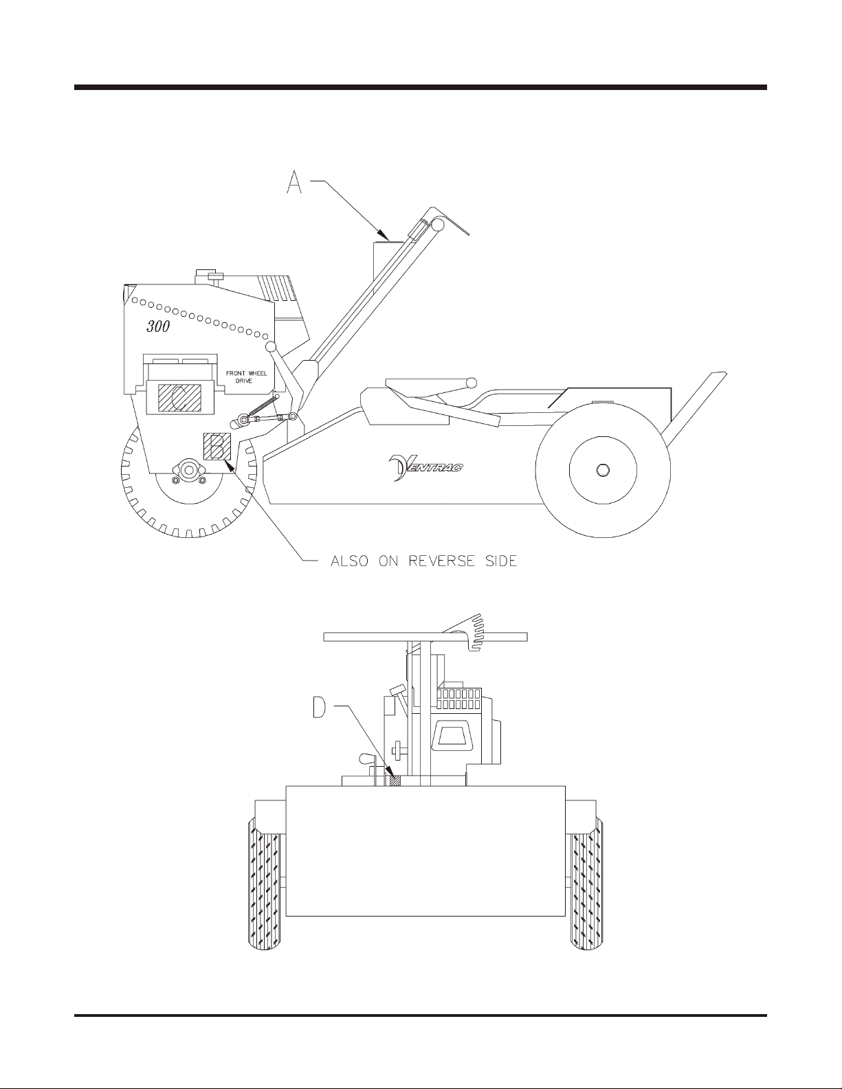
Safety Decal Locations
SAFETY
B-3

B-4
SAFETY
General Safety Procedures
for Ventrac Tractors, Attachments, & Accessories
Read and understand the operator’s manual before operating this equipment.
Observe and follow all safety decals.
DO NOT let children or any untrained person operate the tractor or attachment. Make sure
that all operators of this equipment are thoroughly trained in using it safely.
Never allow additional riders on the tractor or attachments.
DO NOT operate tractor or attachments if you are under the influence of alcohol, drugs, or
medication that may impair judgment or cause drowsiness, or if you are not feeling well.
Operate all controls from the operators seat only.
Before operating equipment, make sure all shields are in place and fastened.
Ensure the attachment or accessory is locked or fastened securely to the tractor (power unit)
before
operating. See tractor manual for locking procedure.
Ensure that all bystanders are clear of the tractor and attachment before operating. Be
especially careful and observant if other people are present. Never assume that bystanders
will remain where you last saw them.
Always look in the direction the tractor is moving.
Never direct the discharge of any attachment in the direction of people, animals, buildings,
vehicles, or objects of value.
Stop operation immediately at any sign of equipment failure and correct the problem before
continuing to operate. An unusual noise can be a warning of equipment failure or a sign that
maintenance is required.
Before adjusting, cleaning, lubricating, or changing parts on the tractor or attachment, engage
the parking brake, lower the attachment to the ground, stop the engine, and remove the
ignition key.
To prevent the risk of uncontrolled equipment movement on tractors equipped with 2 speed
axles, always shift the transaxle range with the power unit stationary on level ground and with
the parking brake engaged.
If equipment is to be left unattended, engage the parking brake, lower the attachment to the
ground, stop the engine, and remove the ignition key.

SAFETY
B-5
VR300 Safety Procedures
Before making any repairs or adjustments, set
parking brake, shut the engine off, and remove the
key.
Read and understand the operator’s manual before
operating this equipment.
Engine exhaust gases contain poisonous carbon monoxide. Carbon monoxide is odorless,
colorless, and can cause death if inhaled. Avoid inhaling exhaust fumes, and never run the
engine in a closed building or confined area.
Become familiar with all controls and their functions before operating the VR300.
Avoid adverse ground conditions, which can limit performance and stability of equipment, and
could cause serious injury or death.
A safety switch requires the Speed Control Lever to be in the neutral position to start the
engine.
Vary vehicle speed with the Speed Control Lever, not with the engine speed. Always maintain
adequate engine speed during operation of the VR300.
Always check to the rear before moving the VR300 in reverse.
Never allow riders on the VR300.
Never attempt to make sharp turns at a high rate of speed.
While on a hill or slope, NEVER turn the engine off under any circumstance, without first
making sure the parking brake will hold the VR300 in place. Ensure the parking brake is set
before exiting the VR300.
The owner is responsible for proper wheelchair
lockdown. It is important that the wheelchair is held
securely in place at all times during operation.

VEHICLE CONTROLS
OPERATION
C-1
Ignition Switch - Turn key clockwise to
start engine. (Note: Speed control lever
must be in neutral with hand removed
from lever.
Light Switch - For headlight.
Figure 1 - Switch Panel
Figure 2 - Throttle Lever
Throttle Lever - To increase engine speed
move lever to the right. To decrease en-
gine speed move lever to the left.
Figure 3 - Chair Compartment Lever
Chair Compartment Lever - To raise tail-
gate, pull handle back. To lower tailgate,
push handle forward.
Inhaltsverzeichnis
Andere Ventrac Nutzfahrzeug Handbücher


