Vesco Turbinator-2 Handbuch

Turbinator-2
Build Manual
Thank you for your purchase of the Turbinator-2 sport jet by Boomerang RC Jets. This RC Jet IS NOT A TOY and
should only be flown and operated by experienced RC Turbine Pilots. Please seek assistance from an
experienced builder and pilot if you are new to Remote Controlled Turbine Jets.
Turbine Waiver requirements for operation in the United States can be found by visiting the Academy of
Model Aeronautics website. https://www.modelaircraft.org/
By building this model you assume FULL RESPONSIBILITY for the safe operation of this model.
It is assumed that you have built model planes prior to this build. This manual is to be used as more of a
guide than a hard set of instructions.
Let’s get started:
Take your time on each step and enjoy the building process as you progress. There is no better feeling than
flying a model you’ve built. So, take your time, build it right and enjoy many years of successful flights.
If you have built a model airplane in the past you will find that the Turbinator-2 goes together just as any other
model airplane would with common materials and practices being used throughout the build. The kit comes
complete with the necessary hardware, linkages and the landing gear.
You may speed thing up a bit by working on different sections of the airplane at the same time. In other
words, while waiting for the glue to dry on the aileron hinges you can work on the rudder hinges etc….
Step 1) Open the box and inspect for damages. Contact us right away if anything is damaged.
2) This is the best time to tighten up the covering. Using your heat gun or iron go over all surfaces and insure
that the covering is properly adhered to the structure.

3) Find the top of vertical stabilizer and the 10mm aluminum rod. This top half will be glued to the fuselage
using 30 minute epoxy or Hysol. You can use tie wraps for clamps while the glue sets.
Dry fit the 2 parts together and insure proper alignment.
Apply masking tape over the seam and very carefully slice along the seem to separate the 2 halves. This will
help keep the surface clean from excess glue that may run. Do not overload the epoxy. Use only enough to
provide adequate adhesion.
Separate the 2 parts and apply the epoxy. Use the tie wraps to clamp the parts together while the epoxy
cures.

Clean off excess epoxy before it dries with denatured alcohol. Remove the masking tape before the epoxy sets
and clean the area as needed.
3) Locate the control ailerons, rudder and elevators along with the pin hinges for them.
Check the fit of each hinge into the control surface. Also check the fit into the adjoining surface such as
wings and stabs. Will need to remove a bit of the covering around holes as needed.
With slow set epoxy or Hysol, glue the hinges into the control surface first and let them dry completely before
gluing to the corresponding wing or stab. Add a VERY SMALL drop of oil to the hinge pin prior to gluing to
insure the glue doesn’t bind the hinge. Do not get any oil on the shaft of the hinge. If you do clean it off with
alcohol.
Periodically exercise the hinges while the glue is setting to insure they aren’t sticking. Use SLOW SET epoxy
during this operation.
You can install the Flap hinges at this time also using the flat hinges. Make sure the hinges are properly aligned
with the slots before gluing.
Once the glue has set on the control surface you can then install the control surface onto their respective wing
or stabilizer. Take great care and insure that you have proper alignment and that there is sufficient
throws/travel on each control surface.
The Flaps should be set to allow for at least 70 degrees of deflection.
The Ailerons and Rudder should have ¾ inches of travel .
The elevator should have 1 inch of travel.
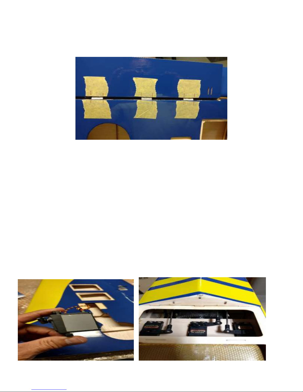
4) While the hinges are drying this is a good time to install servos on the servo covers. Find the covers for
the flaps and ailerons. We recommend at least 150 in oz of torque for all servos. We are running Hitec 5645mg
at 6 volts.
As an added security measure, I have added a layer of double sided tape to each hinge to help secure it to the
cover. Although not necessary it certainly has saved me some headaches in various models over the years.
This is also a good time to install the servos in the fuselage for the Elevators and rudder.

5) Control Horn installation:
The kit comes with composite control horns. You will need to trim the tabs on the horns to fit their
respective control surface properly. Before gluing into the control surface lightly sand the horn to roughen it
up a bit. This will help the epoxy to adhere to the horn.
When installing the horns be sure to install one of the provided ball links between the set of control horns
while the glue is setting. This will insure proper alignment of the 2 horns during installation.
Prior to gluing the horns make sure you gently remove the covering under the backer plate. Do not cut into
the wood. You can apply some thin CA to this area to stiffen it up a bit.

The Flap Control horns are installed facing the rear of the wing. Opposite of the aileron horns which face
forward. This allow for proper clearance at full flap deflection.
6) Push Rod installation: Once all the control horns have been installed on all control surfaces you can begin
installing the push rods. It is best power up your servos and make sure they are centered before installing the
pushrods. This will save you from have to disconnect the rods later to insure the servos are centered. Make
your mechanical adjustments as needed so that all surfaces are as close to center as possible.
The Flap servo should be centered, and the push rod set to the HALF FLAP position. Then you can adjust
endpoints for the no flap and full flap position.
Half Flap 1 ½ inches from bottom of fuse

Zero Flap
Full Flap 2 ½ inches from bottom of fuse
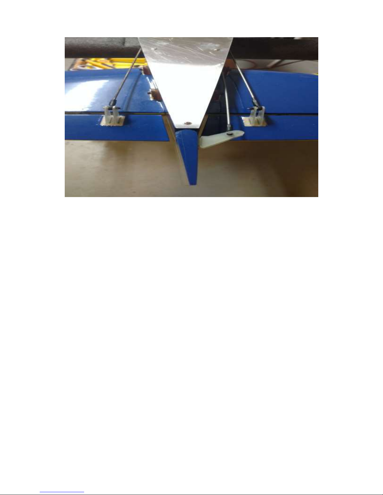
Elevator and Rudder pushrods
7) While I have the wings on the bench I prefer to complete the installation of the gear and tip tanks at this
time. I install the gear first and then the tip tanks. The gear is installed to the mounting blocks with 3mm blind
nuts and screws. This will take some time but is better than wood screws which will come loose over time.
Install one blind nut at a time. If you try and install all 4 at once you run the risk of them not lining up properly.
Again, this is where some patience will pay off.
I chose to modify the brake and retract leads to a standard servo connector. I used opposite ends of the
connector to prevent confusion when hooking them up.

Main Gear installed with 3mm blind nuts.
Leads modified with servo connectors .

8) Tip Tank Installation:
The tip tanks are secured to the wing using 6mm aluminum pins. The pins are held in place by a 4mm screw
on the bottom of the wing.
Install the pins in the wind and leave about half the pin extending from the wing.
Next you will epoxy the tip tank onto the pins. You may have to adjust the hole in the tip tank to insure a
perfect alignment. This can be done with a drill bit and drill and auguring the block in the tip tank as needed.
Once you are satisfied with the alignment of the tip tank go ahead and apply epoxy to both the pin and the tip
tank. Use masking tape or plastic wrap to insure you don’t glue the tank to the wing. I used Hysol for this
operation and let it set overnight.
Masking tape between tip tank and wing
Inhaltsverzeichnis


