VRinsight MCP combo panel Bedienungsanleitung

MCP combo panel
USER MANUAL
1
Please read this manual before operating your
units and keep it for future reference.
Virtual Reality Insight
Virtual Reality Insight
VRinsight
All stated here is subject to change without advanced notice for improvement.
Tel : +82-31-284-7090~91 Fax : +82-31-284-7092 E-mail : [email protected] Web site : www.vrinsight.com

BEFORE USE : Thanks for purchasing VRi’s MCP Combo panel.
Before operating your units, please rea through this manual an keep it for future reference.
For any further question, visit www.wilcopub.com or contact us below:
Fax : +32-2-33107 51
E-mail (Suppor eam) : info@wilcopub.com
NOTE : This manual could be redis ribu ed unless you modify he con en s.
This manual has been wri en ou on a Serial FP v2/Je Liner’s MCP combo
panel basis.
All sof ware (& sof ware versions) s a ed here is subjec o change wi hou advanced
no ice for improvemen .
If you wan o download he la es driver version for panel & applica ion
programs, visi www.vrinsigh .com
2
Box contents

VRinsight MCP combo panel
The MCP combo panel of VRinsigh features various types of aircrafts’ panel with full
control complement ; efault aircrafts of MSFS, most freeware an commercial a -on
aircraft (Wilco’s B737 Classic, PMDG’s B737NG & 744, Level-D’s B767-300 an PSS’
A319,320,330,340). It is completely interface with MSFS9 an MSFSX through a -on
software “VRiSim” which enables MCP combo panel to perform full simulation with
simple connection your computer through USB. Package inclu ing universal power supply
3
simple connection your computer through USB. Package inclu ing universal power supply
a aptor (DC 5V).
The MCP combo panel is comprise of EFIS, MCP & COM (Instrument Ra io) part to
un erstan a vance flight controls for beginners an less a vance users starting flight
simulation games at a first step.
Each control part; EFIS, MCP & COM has push buttons, rotary knobs, toggle S/Ws an /or 2
line character type LCDs offers actual flight circumstance with full control complement.
•VRiSim suppor s all func ions o MCP combo panel
•MCP combo panel consumes high power. To avoid malfunc ion , do no use many o her
USB in erfacing devices. We recommend using ex ernal power supply (DC 5V adap or)
•If you wan o use a USB hub, be sure ha he USB hub is USB 2.0 complian .
O herwise i may cause a malfunc ion.

The MCP combo panel features the following controls:
EFIS par :
- Toggle S/Ws for VOR1,2/ADF1,2 .
- Knob S/Ws for MINS, BARO, CTR ; ND mo e selector an TFC.
- Push buttons for FPV, MTR, WXR, NAVAID, WPT, ARPT, DATA
- All buttons an rotary knobs are user-programmable
EFIS part MCP part COM part
4
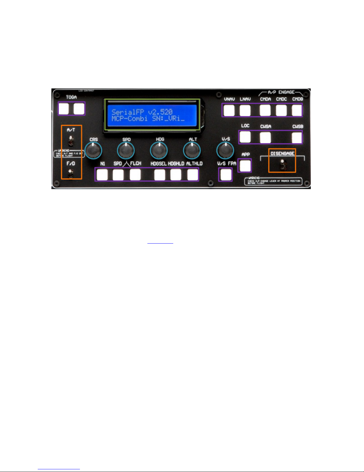
MCP par :
- 2 line character type LCD isplaying SPD, HDG, ALT an Pitch & Bank
at Autopilot Status
- On/Off toggle S/Ws for F/D, A/T
- Thrust mo e selection buttons: N1, SPD, FLCH
- Push buttons for HDG SEL & HOLD, ALT HOLD, V/S SEL, TOGA, CRZ,
VNAV, LNAV, CMDA, CMDB, CMDC, LOC, CWSA(Y/D), CWSB(BCRS),
APP
- On/Off toggle switch for DISENGAGE.
COM(Ins rumen Radio) and 8-User programmable con rol par :
- 2 line character type LCD isplaying COM & NAVAID Frequencies,
DME istance, spee , VOR ID & CRS, Squawk co e
- 5 push buttons for Instrument ra io function selector
(COM, NAV, ADF, DME, TRANSPONDER)
- Rotary knob for NAVAID’s frequency change, CRS/OBS, Squawk Co e
- TFR button for activating stan -by frequency
- 8 User programmable control buttons

Fea ures
•Integrate unit with full ra io stack function : EFIS part, MCP part, COM
part
•All necessary buttons, switches an LCD panel to input SPD, VOR, HDG
an all other functions for getting close to real flight.
•Offer actual flight circumstance via MCP combo panel with full control
complement
•Full metal cases
•One year warranty
Technical specifica ions
•USB interface type to computer
5
•External power requirement : DC 5V a aptor or USB power supply type to
MCP combo panel. We recommen using DC 5V a aptor.
•50cm(W) x 14cm(H)
•4Kg
Compa ibili y sof ware
•Flight simulator 2004 / FSX by Microsoft
Opera ing sof ware
•VRiSim

VRiSim Ins alla ion
With MCP combo panel, an “Install DVD” is inclu e . When you insert it in DVD river of your
computer, “VRinsight HTML” ocument will be shown. Then click “VRiSim” (operating
software) an install it at a proper fol er.
“VRiSim” is the main operating software of VRinsight use for all VRinsight flight panels.
VRiSim software supports full functions of MCP combo panel an completely interface with
MSFS9 an MSFSX enables full simulation with simple connection with your computer
through USB.
Be sure ha when ins alling VRiSim, “Ins all USB-Serial Driver” mus be checked.
After installation, you can fin “SeiralFP2” in “All programs” of “Start menu”.
USB Connec ion
The connection between MCP combo panel an your computer is ma e using a USB cable
that plugs into an USB port on your computer. If you wan o use a USB hub, be sure ha he USB
hub is USB 2.0 complian . O herwise i may cause a malfunc ion.
When you connect MCP combo panel to your computer at first, your computer will etect it
6
When you connect MCP combo panel to your computer at first, your computer will etect it
an will escribe the process step by step.
Power Connec ion
Power supplying of MCP combo panel is one by universal power supply a aptor DC 5V
(Inclu e in package) an /or USB port of your computer. Make sure that before trying to
operate MCP combo panel, you must confirm the USB connection first in or er to prevent
malfunction.
Before trying to operate, be sure that LCD isplaying is shown.
Run “VRiSim”
When you confirm all setup processes one; “VRiSim” installation, “USB connection” an
“Power connection”, you are rea y to operate MCP combo panel.
Download & ins all “FSUIPC”
Refer o “Download & ins all FSUIPC” a “Download” par of www.vrinsigh .com
FS 9 requires FSUIPC v3.80 or later. FSX requires FSUIPC v 4.26 or later.

EFIS part controls explanation
7
EFIS (Elec ronic Fligh Ins rumen Sys em) : It is use to control the respective Primary
Flight Display (PFD) an Navigation Display (ND). EFIS panel inclu es controls for selecting
various mo es an ranges on the ND as well as switches to isplay NAVAIDS, waypoint,
airports an etc. Two toggle S/Ws allow isplaying of the left an right VOR an ADF
bearing pointer on the ND. Controls are available to set barometric altimeter settings for
isplaying on the PFD.
•The func ions of each bu on and knob can be differed from he explana ion according o
he aircraf 's implemen a ion. Also, bu ons and knobs are user programmable for ano her
func ionali y.

L or R VOR / ADF switch : Select NAVAID between VOR or
ADF.
Pushing : Resets or blanks PFD display
Rotating : Adjusts PFD radio or baro minimums altitude
Pushing : Displays preselected barometric setting
Rotating : Adjusts barometric reference
Pushing : Displays full compass rose for APP, VOR and
MAP modes. Subsequent pushing alternates between
expanded and centered displays
Rotating : Changes ND(Navigation Display) mode among
APP, VOR, MAP, PLN.
MIN
S
CTR
BAR
O
Toggle
S/W
8
APP, VOR, MAP, PLN.
APP : Approach mode, displays ILS, localizer and glide
slop information in heading up format. Reference ILS
receiver, ILS frequency or identification, course and DME
VOR : VOR mode, displays VOR navigation information in
heading up format. Reference VOR receiver, VOR
frequency or identification, course and DME and
TO/FROM information
MAP : Map mode, displays FMC-generated route and
map information airplane position, heading and track in
tracking-up format. Displays waypoints, including the
active waypoint within the selected range. Also displays
VNAV deviation
PLN : Plan mode, displays a stationary true north-up route
depiction. Route may be reviewed selecting “STEP” at
using the CDU legs
Pushing : Displays TCAS information on the ND
Rotating : Selects the desired ND nautical miles range
scale
TFC
Rotate &
Push

FPV Displays flight path vectors on PFD
MTRS Displays PFD altitude meters indications
MAP buttons : Selects or removes ND information. More than
one displayed may be selected at a time
WXR Displays weather radar information
STA
Displays high and low altitude navigation aids in the 10, 20 or
40 NM range and high altitude navigation aids only if range is
selected above 40 NM
WPT
Displays waypoints if range selector is set to 10, 20 or 40 NM
9
WPT
Displays waypoints if range selector is set to 10, 20 or 40 NM
ARPT Displays airports information ; ID, distance and etc
DATA Displays the FMC estimated time of arrival and altitude at
each waypoint
POS Displays ADIRU and both GPS positions and VOR raw data
radials extended from the nose of the airplane to the stations.
TERR
Displays the Enhanced Ground Proximity Warning System
terrain data on the ND. The data is mutually exclusive of
WXR data, so selecting one deselects the other.
Between WXR and TERR the priorities are :
•Terrain warning
• Predictive wind shear warning
• Terrain caution
• PWS caution
Push SW
MCP part controls explanation
MCP (Mode Con rol Panel) : It provi es control of the Autopilot, Flight Director, Altitu e
alert an Auto-throttle System. The MCP is use to select an activate Autopilot Flight
Director System, (AFDS) mo es an establish altitu es, spee s an climb/ escent profiles.
* All buttons on the panel are user programmable. How to program the buttons are
explaine at “Panel interface” in “
Downloa
” part.
10
explaine at “Panel interface” in “
Downloa
” part.
Inhaltsverzeichnis
Beliebte Avionik-Display Handbücher anderer Marken

Smart Avionics
Smart Avionics PB-4 Bedienungsanleitung

Midcontinent
Midcontinent SAM MD302 Handbuch

MGL Avionics
MGL Avionics Stratomaster Maxi Single FF-3 Bedienungsanleitung

Garmin
Garmin GI 275 Bedienungsanleitung

Mid-Continent Instruments
Mid-Continent Instruments 4300 Series Handbuch

Avidyne
Avidyne 700-00182 Series Service-Handbuch


