SECTION I
INTRODUCTION AND GENERAL DESCRIPTION
SCOPE
This instruction manual provides instructions for operation, calibration, and
maintenance of WAVETEK Series 150 Programmable Voltage-Controlled Gen-
erators.
GENERAL DESCRIPTION
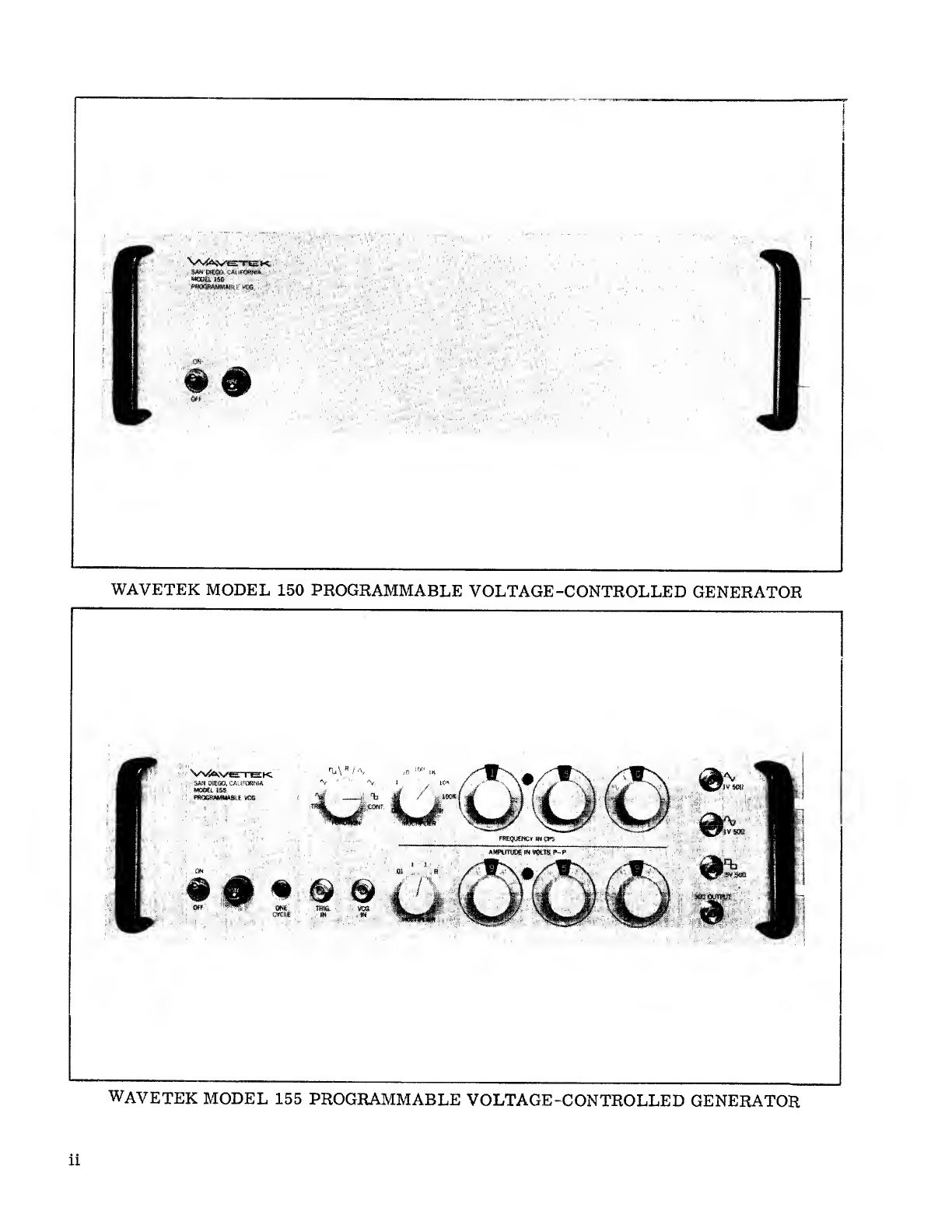
The WAVETEK 150 Series Programmable Voltage-Controlled Generators are
solid-state, multi-purpose function generators which produce sine, triangle
and square wave outputs. The 150 Series includes the Model 150 and the Model
155. Both models are completely programmable, using binary-coded-deci-
mal (BCD) control of frequency and amplitude. Frequency, waveform function,
and signal amplitude are selected by remote contact closures or logic levels.
Both models provide continuous and triggered operating modes. The Model
155 also includes local control by front panel digital switches which allow man-
ual control of frequency, waveform function, amplitude, and range.
The programmed BNC output of the 150 Series instruments provides any one of
the three waveform signals at any amplitude between 10 millivolts and 10 volts,
peak to peak, into a50jt load. The output frequency range is 0. 01 Hz to 1MHz,
in eight ranges. An analog voltage input (VCG) will vary the frequency through
each range to amaximum of Z0:1.
Both models also provide simultaneous sine, triangle, and square wave outputs
with constant amplitude over the entire frequency range of the instrument. The
output impedance of all outputs is 50rL.
The output signals may be continuous or may be triggered by a5volt gate or
pulse input. The trigger input may be specified for either polarity. In the trig-
gered mode, at least one complete cycle is generated for each trigger pulse.
The frequency of the cycle is determined by the programmed frequency and
range. If agate voltage is applied to the trigger input, numerous cycles at the
programmed frequency are generated during the period of the gate. Atrigger
pulse of shorter duration than one cycle of the frequency being generated will
produce one cycle.
Series 150 instrument are 5-1/4 inches high, 16 inches deep, and 19 inches
wide, and are contained in an enclosure which fits astandard RETMA 19-inch
relay rack. The solid-state electronic circuits are contained on plug-in glass-
epoxy circuit boards, interconnected through amother board. An extender
board is included in each instrument, to allow circuit boards to be operated
while extended outside the enclosure. The modular construction facilitates
1-1