Weco Discovery 220T Evo Bedienungsanleitung
Cod. 006.0001.2020
16/11/2021 V.2.1
Discovery 220T Evo/VRD Evo
Discovery 300T Evo/VRD Evo
Instruction manual
ENG
Translation of original instructions

Cod. 006.0001.2020
16/11/2021 V.2.1 Discovery 220T Evo/VRD Evo
Discovery 300T Evo/VRD Evo
2

Cod. 006.0001.2020
16/11/2021 V.2.1
Discovery 220T Evo/VRD Evo
Discovery 300T Evo/VRD Evo
3
Cod. 006.0001.2020
16/11/2021 V.2.1 Discovery 220T Evo/VRD Evo
Discovery 300T Evo/VRD Evo
4
1 INTRODUCTION
IMPORTANT!
This handbook must be consigned to the user prior to installation and commissioning of the unit.
Read the "General prescriptions for use" handbook supplied separately from this handbook before
installing and commissioning the unit.
The meaning of the symbols in this manual and the associated precautionary information are given in
the "General prescriptions for use”.
If the "General prescriptions for use" are not present, it is mandatory to request a replacement copy
from the manufacturer or from your dealer.
Retain these documents for future consultation.
LEGEND
DANGER!
This pictogram warns of danger of death or serious injury.
WARNING!
This pictogram warns of a risk of injury or damage to property.
CAUTION!
This pictogram warns of a potentially hazardous situation.
INFORMATION
This pictogram gives important information concerning the execution of the relevant operations.
Thissymbolidentiesanactionthatoccursautomaticallyasaresultofapreviousaction.
Thissymbolidentiesadditionalinformationorareferencetoadifferentsectionofthemanual
containing the associated information.
§ Thissymbolidentiesareferencetoachapterofthemanual.
*1 The symbol refers to the associated numbered note.
NOTES
Theguresinthismanualarepurelyguidelineandtheimagesmaycontaindifferenceswithrespectto
theactualequipmenttowhichtheyrefer.

Cod. 006.0001.2020
16/11/2021 V.2.1
Discovery 220T Evo/VRD Evo
Discovery 300T Evo/VRD Evo
5
1.1 INTRODUCTION
Discovery220T/300TEvo/VRDEvoisaninverter-basedweldingpowersourcecompletewithallthe
functionsrequiredforDCTIGandMMAweldingwithexcellentarccharacteristics.
Thesolidityofthecomponentsofthisunitmakesitareliableworkingcompanionforworkshopand
outdoor applications.
This unit is ideal for maintenance, food industry, hydraulics, oil pipelines and chemical plants.
TheparameterspresetintheDCTIGpulsedsynergiccurvesimplifyweldingbyregulationexclusively
of the current.
ThecurrentisadjustablealsofromtheUp-Downtorch.
Thesimplyandintuitiveinterfaceallowshighprecisionadjustmentswith50storableprograms.
Thewiderangeofadjustablepulsed frequencyincombination withthecomplementary parameters
(basecurrentanddutycycle)makesitpossibletoweldinslowandfastpulsedmode.
Accessories/ancillary devices that can be connected to the unit:
- manualremotecontrolforremoteadjustmentoftheweldingcurrent.
- foot-pedalremotecontrolforTIGtorcharcstrikingandremoteadjustmentofweldingcurrent.
- UP/DOWNtorchortorchwithpotentiometer.
- liquid cooler for TIG torches.
Consultyourdealerforanupdatedlistofaccessoriesandthelatestnewproductsavailable.
Cod. 006.0001.2020
16/11/2021 V.2.1 Discovery 220T Evo/VRD Evo
Discovery 300T Evo/VRD Evo
6
2 INSTALLATION
DANGER!
Lifting and positioning
Read the warnings highlighted by the following symbols in the “General prescriptions for use”.
2.1 CONNECTIONS TO THE ELECTRICAL MAINS NETWORK
Themainspowersupplyfeaturestowhichtheequipmentshouldbeconnectedaregiveninchapter“12
TECHNICAL DATA” at page 57.
The machine can be connected to motorgenerators provided their voltage is stabilised.
Connect/disconnectthevariousdeviceswiththemachineswitchedoff.
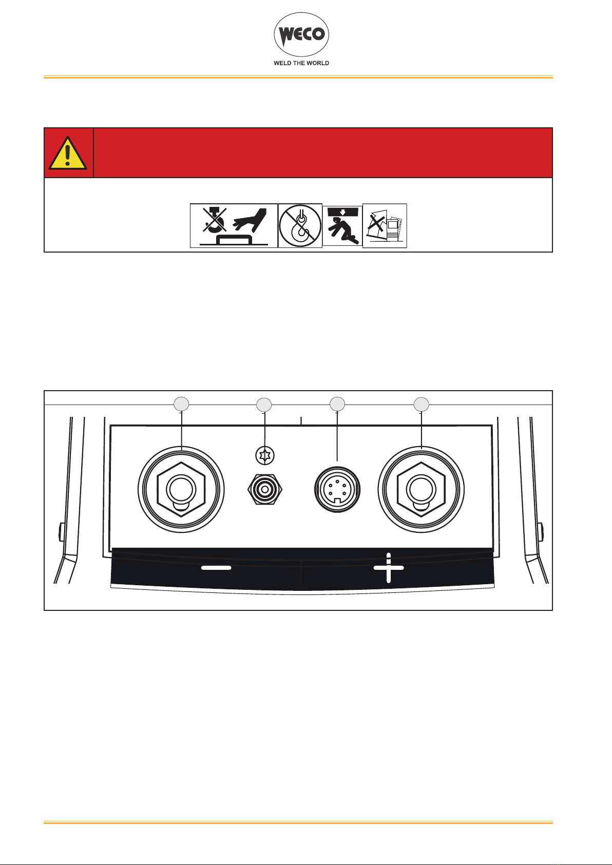
2.2 FRONT PANEL
1234
○ Negativepoleweldingsocket.[Item1].
○ Connectorforgasfeedhose:gasowfromthepowersourcetothetorch.[Item2].
○ TIGTORCHcontrolconnector[Item3].
○ Positivepoleweldingsocket.[Item4].
Cod. 006.0001.2020
16/11/2021 V.2.1
Discovery 220T Evo/VRD Evo
Discovery 300T Evo/VRD Evo
7
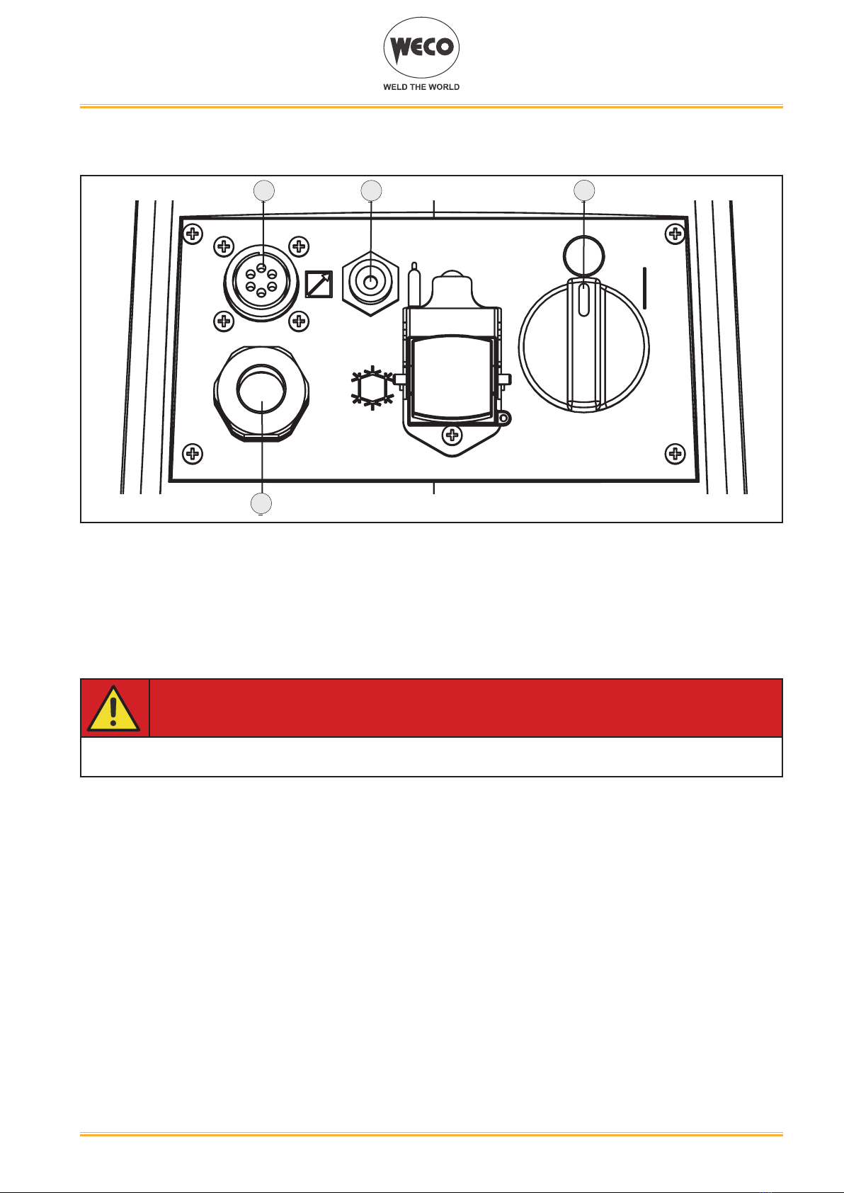
2.3 REAR PANEL
1 2 4
5
○ Remotecontrolconnector[Item1].
○ Connectorforgasfeedhose:gasowfromthecylindertothepowersource[Item2].
○ Coolingunitpowerfeedingconnector[Item3].
• Voltage: 230 V a.c.
• Current output: 1.35 A
• IP protection rating: IP20 (cap open) / IP66 (cap closed)
DANGER!
High voltage!
If the socket is not connected to any devices always close the cap
○ WeldingpowersourceON/OFFswitch[Item4].
○ Powercable.[Item5].
• Length (outer side): 2,05 m
• Numberandcrosssectionofwires:3x2.5mm2(on 220T Evo/VRD Evo)/4x2.5mm2(on
300T Evo/VRD Evo)
• Powerplugtype:Schuko250Va.c./16A(on220T Evo/VRD Evo) / not supplied (on 300T
Evo/VRD Evo)
Cod. 006.0001.2020
16/11/2021 V.2.1 Discovery 220T Evo/VRD Evo
Discovery 300T Evo/VRD Evo
8
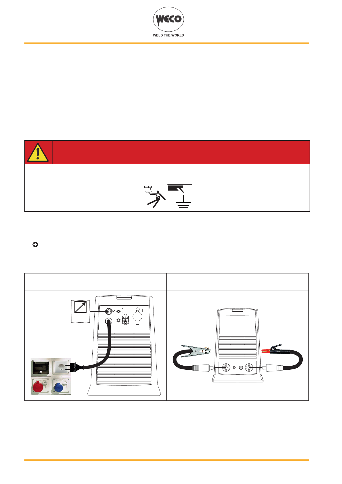
2.4 PREPARING FOR MMA WELDING
1. SettheweldingpowersourceON/OFFswitchto“O”(unitswitchedoff).
2. Plugthepowercableplugintoamainssocketoutlet.
3. Choosetheelectrodebasedonthetypeofmaterialandthicknessoftheworkpiecetobewelded.
4. Insert the electrode in the electrode holder.
5. Connecttheelectrodeholdercabletotheweldingsocketbasedonthepolarityrequestedbythe
type of electrode used.
6. Connecttheplugofthegroundclamptotheweldingsocketonthebasisofthepolarityrequired.
7. Connecttheearthclamptotheworkpiecebeingprocessed.
DANGER!
Electric shock hazard!
Read the warnings highlighted by the following symbols in the “General prescriptions for use”.
8. SettheweldingpowersourceON/OFFswitchto“I”(unitpowered).
9. Selectthefollowingweldingmodeontheuserinterface:MMA
10.Settherequiredweldingparametervaluesontheuserinterface.
Whentheremotecontroller[RC]isconnectedandtherelativelockingscrewistightened,welding
current can be adjusted using the remote controller.
Thesystemisreadytostartwelding.
REAR VIEW FRONT VIEW
(polarity to basic electrode)
REMOTE
CONTROL
Cod. 006.0001.2020
16/11/2021 V.2.1
Discovery 220T Evo/VRD Evo
Discovery 300T Evo/VRD Evo
9
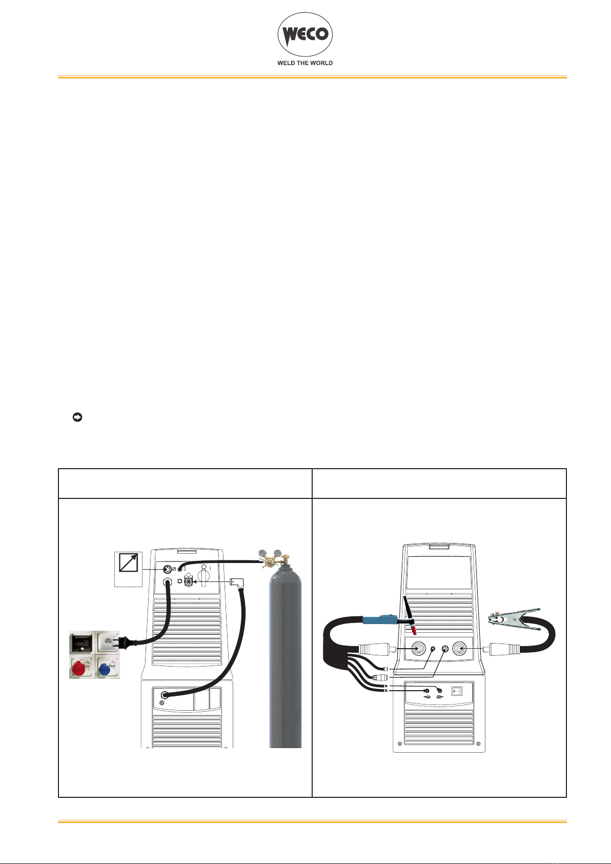
2.5 PREPARING FOR TIG WELDING
NOTE: For the cooler to power source assembly procedure refer to the cooler instruction
manual.
1. SettheweldingpowersourceON/OFFswitchto“O”(unitde-energized).
2. Plugthepowercableplugintoamainssocketoutlet.
3. Connectthegashosefromtheweldinggascylindertothereargassocket.
4. Open the cylinder gas valve.
5. Choosetheelectrodebasedonthetypeofmaterialandthicknessoftheworkpiecetobewelded.
6. Insert the electrode in the TIG torch.
7. Connectthetorchplugtotheweldingsocketonthebasisofthepolarityrequiredbythetypeof
electrode in question.
8. Connecttheplugofthegroundclamptotheweldingsocketonthebasisofthepolarityrequired.
9. Connectthegashosefromtheweldingtorchtothefrontgassocket.
10.ConnecttheweldingtorchconnectortotheTIGtorchsignalsconnector.
11.Connecttheearthclamptotheworkpiecebeingprocessed.
12.SettheweldingpowersourceON/OFFswitchto“I”(unitpowered).
13.Selectthefollowingweldingmodeontheuserinterface:DCTIG
14.Pressthetorchtriggerwiththetorchwellclearofanymetalparts.Thisservestoopenthegas
solenoidvalvewithoutstrikingtheweldingarc.
15.Usetheowcontrolvalvetoadjusttheowofgasasrequiredwhilethegasisowingout.
16.Settherequiredweldingparametervaluesontheuserinterface.
Whentheremotecontrolpedalisconnectedandtherelativelockingscrewistightenedtheweld-
ingcurrentwillvaryinrelationtothepressureexertedonthepedal.
Thesystemisreadytostartwelding.
REAR VIEW FRONT VIEW
(polarity for tungsten electrode)
REMOTE
CONTROL
Cod. 006.0001.2020
16/11/2021 V.2.1 Discovery 220T Evo/VRD Evo
Discovery 300T Evo/VRD Evo
10
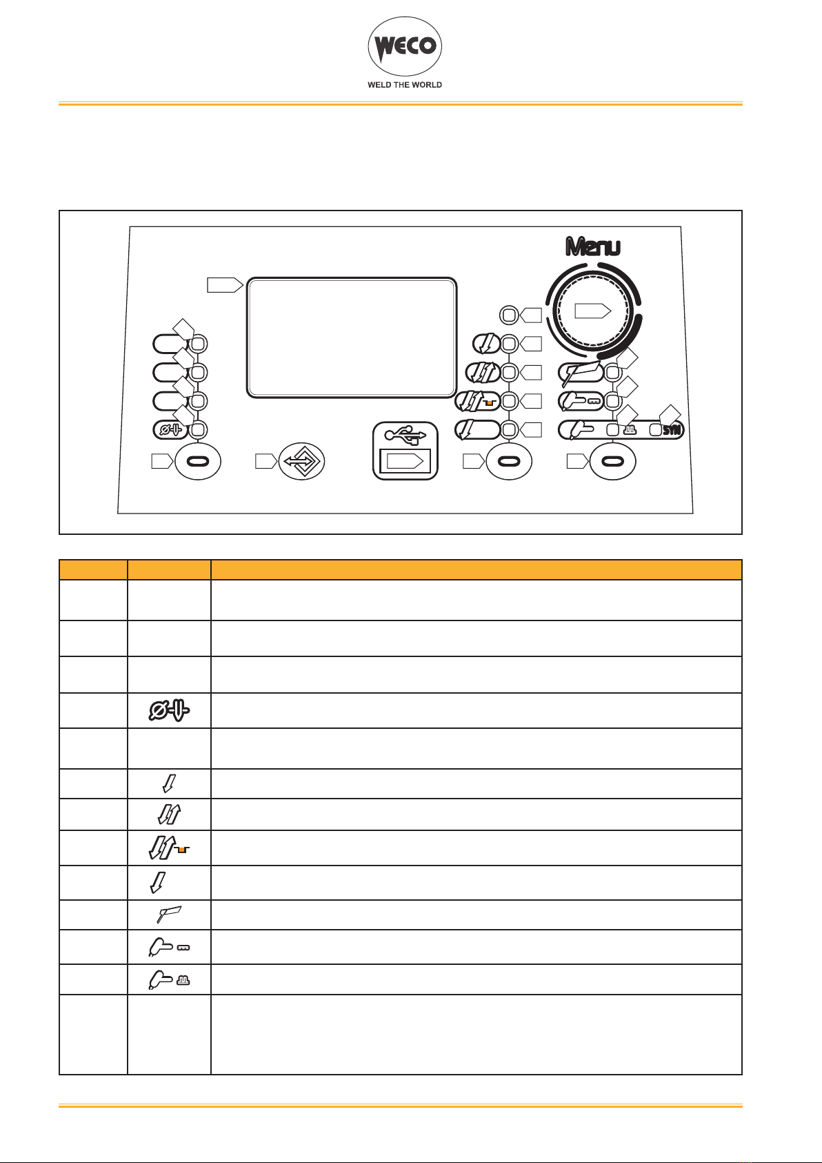
3 USER INTERFACE
Discovery 220T Evo/VRD Evo - Discovery 300T Evo/VRD Evo
DYN arc
QST
M-TACK
MenuMenu
Q-SPOT
HF E1/S5
S3
L1
D1
USB S4S2S1
L2
L3
L4
L5
L6
L7
L8
L9
L10
L11
L12
SYNSYN
L13
CODE SYMBOL DESCRIPTION
L1
QST
DCTIGmode:illuminationshowsthatthefollowingparametercanbeset:Q-START
L2
DYN arc
DCTIGmode:illuminationshowsthatthefollowingparametercanbeset:DYNAMICARC
L3
M-TACK
DCTIGmode:illuminationshowsthatthefollowingparametercanbeset:MULTITACK
L4 DCTIGmode:illuminationshowsthatthefollowingparametercanbeset:ELECTRODEDIA-
METER (mm)
L5
HF
Illumination shows that the following function has been activated: HIGH FREQUENCYARC
STRIKE (HF)
L6 Illuminationshowsthatthefollowingfunctionhasbeenactivated:2strokeprocedure.
L7 Illuminationshowsthatthefollowingfunctionhasbeenactivated:4strokeprocedure.
L8 Illuminationshowsthatthefollowingfunctionhasbeenactivated:4strokeB-levelprocedure
L9
Q-SPOT
Illuminationshowsthatthefollowingfunctionhasbeenactivated:2strokespotprocedure(Q-
SPOT).
L10 ThisLEDilluminatestoshowthatthefollowingweldingmodeisselected:MMA
L11 ThisLEDilluminatestoshowthatthefollowingweldingmodeisselected:CONTINUOUSDC
TIG
L12 ThisLEDilluminatestoshowthatthefollowingweldingmodeisselected:PULSEDDCTIG
L13
SYN
ThisLEDilluminatestoshowthatthefollowingweldingmodeisselected:SYNERGICPULSED
DC TIG
When this is on, it means that the synergic mode is active and that the operator can set just the
weldingcurrent whilethe otherparametersareautomaticallyregulatedbythemachine.The
synergyisoptimisedforanglewelding.
Dieses Handbuch passt für folgende Modelle
3
Inhaltsverzeichnis
Andere Weco Schweißzubehör Handbücher


Beliebte Schweißzubehör Handbücher anderer Marken

Lincoln Electric
Lincoln Electric LT-7 Tractor Bedienungsanleitung

Cornwell Tools
Cornwell Tools MMWC1 Bedienungsanleitung

Dohle
Dohle ExOn2A Bedienungsanleitung

Nederman
Nederman Fume Eliminator FE 840/2500/P150 Bedienungsanleitung

3M
3M Speedglas 9100 Series Bedienungsanleitung

Miller Electric
Miller Electric OM-842 Bedienungsanleitung

Miller
Miller A-200 Series Bedienungsanleitung

Abicor Binzel
Abicor Binzel ABIMIG WT Series Bedienungsanleitung

optrel
optrel lifeflip autopilot Bedienungsanleitung

Miller
Miller MIGmatic M-25 Bedienungsanleitung

Tregaskiss
Tregaskiss TOUGH GUN TT3 Reamer Bedienungsanleitung

Abicor Binzel
Abicor Binzel xFUME PRO Bedienungsanleitung


