Xflighttech AUTOPILOT / TRIM Fehlerbehebungshandbuch

Xflight Technologies LLC
AUTOPILOT / TRIM User & Installation Guide
Version 3.4
(Mini Pix Flight Controller)
July 2020
Xflighttech.com

Copyright © 2019 Xflight Technologies LLC, Florida, USA
2
A. Terms, Conditions and Warranty.
These products are only intended to be used in LSA Class Experimental Aircraft or Ultralights
(as defined by the FAA in the USA) under the full responsibility of the pilot. AHRS and
Autopilot components are intended to be used for informational purposes or to manipulate
secondary control surfaces only, allowing the pilot full manual control of the aircraft
See Appendix A for details
B. Setup and Connection:
1. Ensure the Display is firmly seated and connected via the HDMI connector
2. Connect the GPS antenna to the Flight Controller GPS/12C socket
3. Connect the Flight Controller micro USB Link to one of the Raspberry Pi (AUTOPILOT) USB
sockets
4. Connect the 5v DC power supply to the Raspberry Pi (AUTOPILOT) micro USB connector
(A backup power supply may be used and connected to the touchscreen micro USB connector)
5. Connect the Power Module to the Flight Controller and battery (via AP switch & fuse circuit)

Copyright © 2019 Xflight Technologies LLC, Florida, USA
3
6. Safety Enable should already be connected from the Flight Controller to the Raspberry Pi
(AUTOPILOT) GPIO pins 32 & 30
7. Servo Test Switch should already be installed in the Raspberry Pi (AUTOPILOT) GPIO pins 33 & 34
(this can be removed once calibration is complete)
8. Connect the Wi-Fi module to the TELEM1 port of the Flight Controller
9. Connect the TRIM system to the 5v power supply and to the Flight Controller
10. Connect the yoke trim switches to the TRIM System (see details in section F)
11. Make sure the SD card (AUTOPILOT software) is firmly seated inside the Raspberry Pi and the SD
card in the Flight Controller is also firmly seated (used for logging)
C. Installation Overview
Additional details in section F.
1. Mount the Flight Controller horizontally facing forward, sitting on a padded or foam base to
reduce vibration. (Adjustments for setting perfect level and for tail-wheel aircraft will be
covered later, under section G - Calibration).
2. Mount the GPS antenna on the dash or somewhere with line of sight to the sky, facing forward.
3. Connect the AUTOPILOT power supply and TRIM System power supply to the battery via a
separate switch and 10A fuse. Use a separate switch and fuse for the servo power circuits.
4. When installing the AUTOPILOT behind the instrument panel, it is necessary to ensure there is
an insulated layer between the touchscreen display surface and the metal panel for proper
operation. The plastic frame of the case makes for a good insulating layer.

Copyright © 2019 Xflight Technologies LLC, Florida, USA
4
D. Startup
1. Leave servos switched off until you are ready to use the Autopilot in flight. Always power up the
AUTOPILOT circuit first.
2. Make sure you are outside with a view to the sky. Upon startup the AUTOPILOT will connect to
the Flight Controller, maintaining a heartbeat (ignore the login prompt). If the Flight Controller is
not able to lock onto more than 5 satellites, the AUTOPILOT will keep trying, via a countdown. If
it still cannot get a good lock after the countdown, it will start up anyway, and you will be able
to see the satellite count for yourself. It will be red if below 6, otherwise green. A red cross will
appear if the satellite count is less than 5. (A flashing green light on the GPS antenna also
indicates satellites have been acquired). If the satellite count is zero you will need to restart.
3. Make sure the Flight Controller remains stable during startup. Once the AUTOPILOT has started
it will lock in the current GPS location, and use this as its Home reference.
4. If either the Flight Controller link is broken (loss of heartbeat) or the satellite count falls below 5,
you will see a large red cross appear on the display and the AUTOPILOT will disengage. The AHRS
is still working, but the flight data readings cannot necessarily be trusted. Once the AUTOPILOT
has reconnected, and/or the satellite count goes back up to 5 or above, the AUTOPILOT will
resume normal operation.
Copyright © 2019 Xflight Technologies LLC, Florida, USA
5
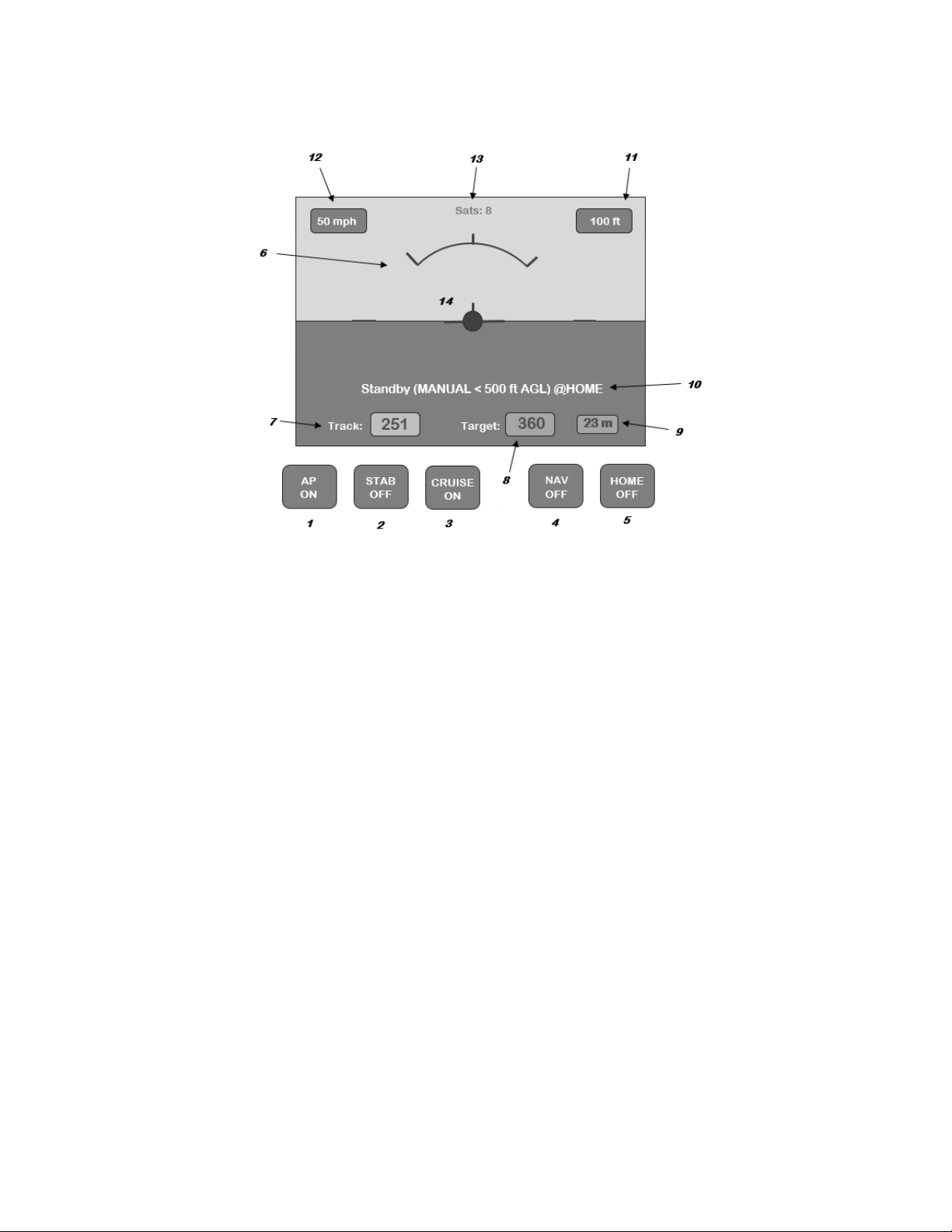
E. Operation:
When operating normally the display will provide a smooth indication of attitude as well as the
various flight data parameters detailed below.
1. AUTOPILOT ON/OFF
•Switches the AUTOPILOT ON in Manual flight mode, ready for an automated flight mode
to be set (i.e. STAB, CRUISE, NAV, HOME). This also enables the Servo PWM signals,
starts flight logging (and enables the Trim switches if applicable)
•Switches the AUTOPILOT OFF, switches back to Manual flight mode, setting all other
automated modes OFF. This also disables the Servo PWM signals, stops flight logging
2. STABILIZATION Mode (Wings Level) ON/OFF
•Seeks to maintain wings level. Altitude/pitch unaffected
3. CRUISE Mode (Heading & Altitude) ON/OFF
•Seeks to maintain current heading (Target) and current Altitude
•The minimum altitude is 500 feet AGL for this mode at the Home location. (If below 500
feet AGL at the Home location, the AUTOPILOT will climb to this minimum altitude when
in Cruise mode)
4. NAV Mode WAIT/ON/OFF
•Switches the AUTOPILOT into NAV WAIT (olive) mode, waiting for the mobile app to
upload and start a flight plan / mission

Copyright © 2019 Xflight Technologies LLC, Florida, USA
6
•Once the flight plan / mission has been uploaded and started will switch to ON (Green)
and start to execute the mission
•OFF (red) switches NAV mode off and returns to MANUAL flight mode
5. HOME Mode ON/OFF
•Return to Home location or RTL (Return To Land), at current altitude
•The aircraft will turn on to a heading back to the Home location with a maximum bank
angle of 20 degrees (configurable). When within 1mile (configurable) of the location it
will perform a 1-mile left hand (configurable) loiter circle and remain overhead the
Home location until the mode is deselected.
•This button will flash green/blue when within two miles of Home location
6. Bank angle graduations: 0, 30, 45, 60 degrees
7. Current heading (continuously displayed, regardless of mode)
8. Target Track (to Home location when in Home mode or Cruise track when in Cruise mode)
9. Ground distance to Home location in miles (continuously displayed, regardless of mode)
10. AUTOPILOT Status
•This displays current Flight Controller status - STANDBY/ACTIVE, current AUTOPILOT
mode and if at Home location
•STANDBY: Aircraft is on the ground, ready for flight
•ACTIVE: System is active, and aircraft may already be in flight
11. GPS Altitude above mean sea level (AMSL) in feet (continuously displayed, regardless of mode)
12. Groundspeed in miles per hour (continuously displayed, regardless of mode)
13. Number of satellites locked on. If this drops below 5, you will see a large red cross appear on the
display and the AUTOPILOT will disengage (the flight data readings and AHRS will continue to
update but cannot necessarily be trusted). Once the satellite count goes back up to 5 or above,
the AUTOPILOT will be available again
14. When on the ground touching the center yellow reference plane will calibrate the AHRS to
straight & level (AP OFF mode)
15. TRIM System
•A single press of a yoke switch will move the selected control surface a small amount
•Continuously pressing a yoke switch will continuously move the selected control surface
•Simultaneously pressing two opposing yoke switches (pitch up & pitch down or roll left
& roll right) will centralize the selected control surface

Copyright © 2019 Xflight Technologies LLC, Florida, USA
7
F. Physical Installation
Wire AUTOPILOT and servo power circuits separately with their own fuse and switch:
AUTOPILOT, Flight Controller Power Module
and touchscreen (and optional TRIM system)
Switch and 5A fuse (or 10A w/ TRIM system)
Pitch and Roll Servos
Switch and fuse as per servo requirements
A backup power supply may be used and connected to the touchscreen micro USB connector.
1. AUTOPILOT
The optimal location for the AUTOPILOT is behind the instrument panel. (Make sure to leave
sufficient room for the USB connections).
The rectangular cut-out required will be approx. 3 inches x 2 1/4 inches (76mm x 57mm).
Metal instrument panels will require an insulated layer between the touchscreen display surface
and the panel for proper operation. The plastic frame of the case provided makes for a good
insulating layer. Simply remove the 4 screws, mount the AUTOPILOT behind the instrument panel
with the frame in place, and secure the AUTOPILOT with the screws from the front of the instrument
panel.
Overall dimensions of the AUTOPILOT (Raspberry Pi) + Screen are approx. 4” (102mm) x 3” (76mm) x
1.5” (38mm)

Copyright © 2019 Xflight Technologies LLC, Florida, USA
8
2. Flight Controller
The Flight Controller needs to be close to the AUTOPILOT and the GPS antenna which is typically
mounted on the dashboard. Mount the Flight Controller horizontally and flat facing forward,
sitting on a padded or foam base (provided) to reduce vibration, and make sure it cannot move
in flight.
The GPS antenna needs to be installed facing forward as it also has a built-in compass and must
have a good line of sight to the sky. Satellite reception is good through glass, plastic, wood,
fabric, etc., but not through conducting surfaces such as metal.
The Flight Controller (Mini Pix) dimensions are 1.5” (38mm) square x 0.5” (12.7mm)
The GPS antenna dimensions are 1.25” (31.75mm) square x 0.5” (12.7mm)

Copyright © 2019 Xflight Technologies LLC, Florida, USA
9
3. AUTOPILOT / TRIM and Flight Controller Wiring
The Flight Controller, AUTOPILOT and TRIM System all need to be on a separate switched and fused
(5A) circuit to the servo(s) circuit. They need to be powered up at the same time. The AUTOPILOT /
TRIM circuit always needs to be switched on before the servo(s) circuit.
The Trim switch wiring is also shown here. There is a common ground wire and one wire each for
pitch up, pitch down, roll up and roll down switches. The wires are labelled accordingly.

Copyright © 2019 Xflight Technologies LLC, Florida, USA
10
The Safety Enable will already be connected, but for your reference this connects the AUTOPILOT
(Raspberry Pi) pin 32 (GPIO 12 signal) and pin 30 (Ground) to the Flight Controller (Mini Pix) via the special
cable provided (opto-isolator switch):
Dieses Handbuch passt für folgende Modelle
1
Inhaltsverzeichnis


