Yanmar Mase I.S. 6.5 Bedienungsanleitung

GB - INSTALLATIONMANUAL
masemase
masemase
mase
GENERATORS
I.S. 6.5 50 Hz
GENERATORS
- 2 -
IS 6.5
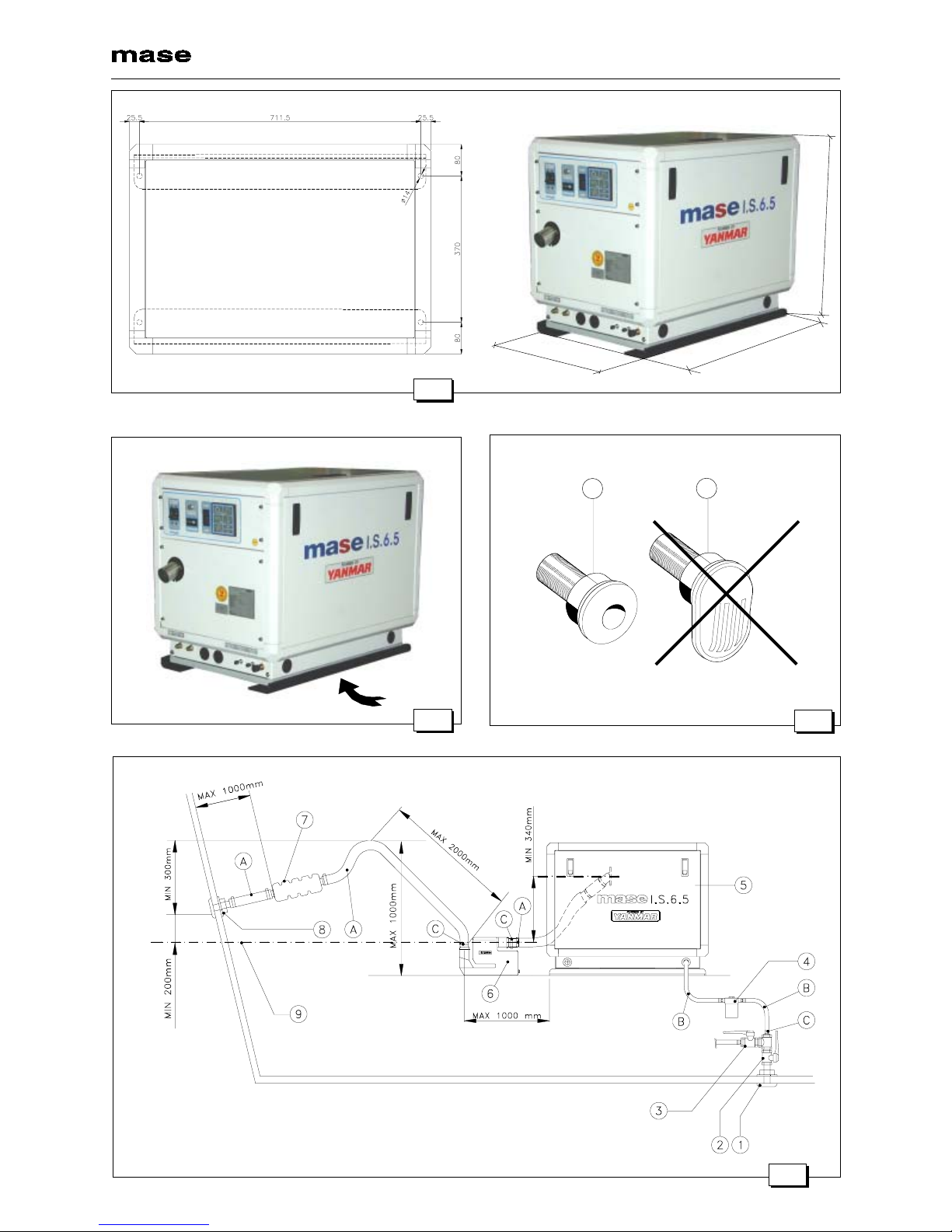
Fig. 1
Fig. 2
12
Fig. 3
Fig. 4
Nomefile: 41814.p65 del 21/04/00
Data di aggiornamento: 30/05/00
Redatto: D.B.
760
625
5 3 0

GENERATORS
- 3 -
IS 6.5
Fig. 7
Fig. 5
Fig. 6

GENERATORS
- 4 -
IS 6.5
Fig. 9
1
Fig. 8
Fig. 12
Fig. 11
Fig. 10
Valvola antisifone
Anti-siphon valve
Soupape antisiphon
Beluchter
1
2
3
4

GENERATORS
- 5 -
IS 6.5
Fig.14
Fig.15
1
Fig. 13
1
2

GENERATORS
- 6 -
IS 6.5
Fig. 17
GEN.
CARICO
LOAD
CHARGE
VERBRUIKERS
RETE
MAINS
RESEAU
WALAANSL
Fig. 16
1

GENERATORS
- 7 -
IS 6.5
Fig. 18
WIRINGDIAGRAM
MACHINE CODE: 001060 - 001096 - 001135 - 001134 - 001129 - 001137
No.FILE:22.29.043-00

GENERATORS
- 15 -
IS 6.5
I
INDEX
Pictures ................................................................................................................................... 2
Wiring diagram ...................................................................................................................... 7
1 GENERALINFORMATION .............................................................................................. 16
1.1 Purpose and field of application of the manual ................................................................. 16
1.2 Symbols .......................................................................................................................... 16
2 Prescriptions for safety during installation and setup ............................................... 17
3 INSTALLATION .............................................................................................................. 17
3.1 Characteristics of the installation space .......................................................................... 17
3.2 Fastening the unit to the ground ...................................................................................... 17
3.3 Ventilation ....................................................................................................................... 17
4 COOLINGWATERCIRCUIT ........................................................................................... 17
4.1 Sea water feed system .................................................................................................... 17
4.2 Typical installation with electric generator above the water-line........................................ 17
4.3 Typical installation with electric generator below the water-line........................................ 18
4.4 Typical installation of electric generator with "E/G" separator above and below
the water-line ................................................................................................................... 18
4.5 Components .................................................................................................................... 18
4.6 Drainage system..............................................................................................................19
5 FUELCIRCUIT ................................................................................................................ 19
6 ELECTRICALCONNECTION .......................................................................................... 19
6.1 Battery connection...........................................................................................................19
6.2 Control panel connection ................................................................................................. 19
6.3 A.C. Connection ..............................................................................................................19
6.4 Generator - Mains Switching............................................................................................ 20
7 LIFTING .......................................................................................................................... 20
8 WIRINGDIAGRAMREFERENCES ................................................................................. 20
GB

GENERATORS
- 16 -
IS 6.5
GB
1 GENERAL INFORMATION
Carefully consult this manual before proceeding with any operation on the generator.
1.1 Purpose and field of application of the manual
Thank you for choosing a mase product.
Thismanualhasbeendrawnupbythemanufacturerwiththepurposeofprovidingessentialinformationandinstructions
for proper installation in conditions of safety and constitutes an integral part of the generator equipment. The manual
must be kept safely, protected from any agent which might damage it, for the entire life of the generator and must
accompany the generator if transferred to another user or owner.
The information contained in the manual is addressed to all those persons involved in the operating life cycle of the
generator, and is necessary to inform both those who effectively carry out the different operations and those who
coordinate the activities, arrange the necessary logistics and regulate access to the place where the generator will be
installed and operated.
The manual defines the purpose for which the generator was constructed and contains all the information necessary
to guarantee safe and proper use.
Constant observance of the instructions contained in this manual guarantees the safety of the operator, operating
economy and a longer life of the generator.
It is warmly recommended to carefully read the contents of this manual and the reference documents; only thus can
regular functioning and reliability of the generator be guaranteed over time, and protection against damage to persons
or things.
The drawings are provided by way of example. Even if the generator in your possession differs considerably from the
illustrations contained in this manual, the safety of the generator and the information provided are nevertheless
guaranteed.
To facilitate consultation, it has been divided into sections identifying the main concepts; for a quick look at the topics,
consult the index.
Note: the information contained in this publication is correct at the time of printing. The manufacturer in his pursuit
of a policy of constant development and upgrading of the product reserves the right to make modifications without prior
notice.
1.2 Symbols
Those parts of the text not to be ignored are highlighted in bold type preceded by a symbol, as illustrated and defined
below.
Indicates that particular attention must be paid in order to prevent runninginto serious danger which
could lead to death or possible hazards to the health of personnel.
A condition which may occur during the lifetime of a product, system or plant considered at risk
regarding damage to persons, property, the environment or economic loss.
Indicates that particular attention must be paid in order to prevent serious consequences which
could result in damage to tangible goods, such as the resources or the product.
Instructions of particular importance.
FAILURE TO RESPECT THE SPECIFICATIONS CONTAINED IN THIS USE AND MAINTENANCE
MANUAL WILL RESULT IN FORFEITURE OF THE GUARANTEE ON THE PRODUCT

GENERATORS
- 17 -
IS 6.5
GB
2 Prescriptions for safety during installation and
setup
- The personnel in charge of installation and starting
of the generator must always wear a protective
helmet, safety shoes and overalls.
- Use protective gloves.
- Do not leave disassembled parts, tools or anything
else not forming part of the system on or near the
engine.
- Never leave inflammable liquids or cloths soaked in
inflammable liquids in proximity of the generator,
near electric equipment (including lamps) or parts
of the electrical system.
- Take the necessary precautions to prevent the
danger of electrocution.
- Check that the earthing system has been installed
and constructed in accordance with regulations.
3 INSTALLATION
3.1 Characteristics of the installation space
The generator must be installed in a sufficiently aired
space, supplying a little amount of air necessary for the
combustion of the motor.
The space must be separate and acoustically insulated
from living areas.
The generator should be positioned so that normal
maintenance operations can easily be carried out.
Propulsion motors are recommended for installation in
the area as long as they comply with the above-men-
tioned conditions.
3.2 Fastening the unit to the ground
To fasten the unit securely, a base should be installed to
absorb vibrations and support the weight.
Drill holes in the base according to the instructions in
fig. 1.
3.3 Ventilation
The generator is equipped with an internal forced cooling
system through a water/air exchanger.
The air needed for combustion is taken in through the
opening on the base (fig. 2) so care must be taken to
ensure that this opening is always free.
4 COOLING WATER CIRCUIT
The engine of generators IS 6.5 / 7.6, is cooled by an
closed circuit system heat exchanger.
On installation a sea water feed circuit should be fitted for
cooling and a waste system to expel the mixture of flue
gas and water.
4.1 Sea water feed system
Boats usually use one of two systems to collect water
(fig. 3):
1- Direct infeed system
2- System with baffle
MASE recommends the direct infeed system (ref.1 fig. 3)
since this system prevents water under pressure enter-
ing the suction ducts and instead forms a pressure which
can easily be overcome by the water pump of the electric
generator.
Do not apply any type of protective
hood to the direct infeed system.
The baffle system might cause the following problems:
a- If it is installed with the slots facing the prow.
In this case, during navigation and with the electric
generator off, pressure is accumulated in the water
infeed duct which might cause the system to fill up,
even as far as the exhaust port, allowing water to
enter the cylinders.
b- If it is installed with the slots facing the stern.
In this case a depression might accumulate in the
water infeed duct during navigation, preventing the
water pump from starting up the cooling plant, or
limiting the capacity and subsequently causing the
electric generator to overheat.
4.2 Typical installation with electric generator
above the water-line (fig. 4)
1Sea intake
2Generaltap-water
3Tap to drain system
4Water filter
5Electric generator
6Barrelmuffler
7Silencer
8Sea drainage nozzle
9Water line
A- Tubes, internal diameter 50 mm
B- Tubes, internal diameter 15 mm
C- Clamps
D- Tubes, internal diameter 50 mm
The measurements shown in fig.
4-5 should correspond exactly.
The muffler (fig.4, ref.6) has the job
of collecting the water in the exhaust pipes when the
generator motor is turned off, thus preventing it from
flowing into the motor through the exhaust manifold
and valve. For this reason it is essential that the
position of the muffler and the length of the pipes
indicated on the installation chart be fully respected.
Inhaltsverzeichnis
Andere Yanmar Tragbarer Generator Handbücher

Yanmar
Yanmar mase Marine I.S. 5.0 Gebrauchsanweisung

Yanmar
Yanmar YDG Series Bedienungsanleitung

Yanmar
Yanmar neoTower Bedienungsanleitung

Yanmar
Yanmar YDG Series Bedienungsanleitung

Yanmar
Yanmar YDG5001SE Bedienungsanleitung

Yanmar
Yanmar TNE Series Bedienungsanleitung

Yanmar
Yanmar LIGHT BOY LB446HB Bedienungsanleitung

Yanmar
Yanmar mase marine I.S. 3.5 Gebrauchsanweisung


